
A Metal Detector for Clip Location Tracking of Stomach and Colon Cancer during Laparoscopic Surgery


1
Medical Devices R&D Center, Gachon University Gil Medical Center, Incheon 21565, Korea
2
Department of Biomedical Engineering, College of Medicine, Gachon University, Incheon 21565, Korea
3
Department of Gastroenterology, Gachon University Gil Medical Center & College of Medicine, Gachon University, Incheon 21565, Korea
4
CAIMI Co., Ltd., #206 Building of Incheon Startup Park, 204 Convensia-daero (Songdo-dong), Yeonsu-gu, Incheon 22004, Korea
5
Department of Biomedical Engineering, College of Health Science, Gachon University, Incheon 21936, Korea
6
Department of Health Sciences and Technology, Gachon Advanced Institute for Health Sciences and Technology (GAIHST), Gachon University, Incheon 21565, Korea
*
Authors to whom correspondence should be addressed.
†
These authors contributed equally to this work.
Appl. Sci. 2022, 12(14), 7330; https://doi.org/10.3390/app12147330
Submission received: 23 June 2022
/
Revised: 18 July 2022
/
Accepted: 19 July 2022
/
Published: 21 July 2022
Abstract
:In laparoscopic surgery for colorectal and gastric cancer, it is difficult to locate the tumor in the cavity for excision. Tumors in the colon or stomach are blocked by mucous membranes; thus, the view from the cavity is obscured. Therefore, to determine the location of the tumor, a marker can be installed around the tumor and the location of the tumor can be found using a sensor. Until now, most of the clip-detectors that have been developed can detect the location of tumors for either colorectal or gastric cancer. The research on the development of a detector that can detect the location of tumors for both colorectal and gastric cancer, is insufficient. Most detectors for tumor location determination are devised using a magnet by connecting a wire to a clip. In this method, the position of the magnet moves along the length of the wire. Therefore, it is difficult for the detector to detect the exact location of the tumor. Based on this method, this study designs a clip maker to determine the location of a tumor and a detector that can detect the clip. The clip and the sensing element are directly connected. The clip is developed using ferrite and coil to generate a magnetic field induced by an eddy current in the metal (clip), and the detector is designed using the Colpitts oscillator to induce a magnetic field. After installing the prepared clip at the tumor location, the detector is used to detect the clip, and accordingly, the location of the tumor can be identified using the detector. To test the performance of the clip and detector, we conducted animal experiments. In the course of the animal experiment, four clips were installed in the colon and stomach, and we succeeded in detecting all the clips. Because the clip-detector is used to locate the tumor during laparoscopic surgery, an endoscope must be used. Therefore, it is predicted that the demand for laparoscopic surgery and endoscopic medical industry will increase because of the clip-detector.
1. Introduction
Colon and stomach cancers ranked between 3rd and 5th around the world from 2020 to 2022 [1,2]. More specifically, the colon and stomach cancer rank 3rd (2020) and 5th (2022) in the world, now [1,2,3]. The endoscopy diagnosis technique and routine screening are being increasingly employed, and the detection of early-stage cancer is enabled by endoscopy screening [2]. For the early-stage cancers detected and removed during routine screening, the five-year survival rate is as high as 90%. Removal of early-stage cancer is possible by laparoscopic surgery. In addition, laparoscopic surgery generally causes less pain and scarring and requires a shorter hospital stay than thoracotomy or laparotomy [2].
It is difficult to detect the benign and malignant tumors in the visceral layer, cardiac orifice, pylorus, circular folds, inferior part (horizontal 3rd), and ascending (#4th) colon (more specifically, in the parietal peritoneum, cecum, middle circular muscle layer, pyloric zone, submucosa, and serosa of the stomach and colon) through laparoscopic surgery. Thus, the prehension of mucosa incision range is difficult for tumor removal; the faulty prehension of mucosa incision range causes errors [2].
In laparoscopic surgery for tumor removal of colon and stomach cancers, the detection of tumor location using marker methods such as ink tattooing, the method using indocyanine green dye and autologous blood labeling, is extremely important. These aforementioned methods have side effects and are disadvantageous [4,5,6,7,8]. Ink tattooing causes the ink outflow (smudge) phenomenon within the abdominal cavity. Thus, the incision range prehension for tumor removal is difficult [4,5]. In addition, the side effect of the ink tattooing method is the formation of peritonitis and granuloma (incarnative), and this method additionally necessitates high proficiency and is extremely expensive. The ICG fluorescein dye marking leads to intraperitoneally bleeding (intraperitoneal) or smudge, an iodine allergic reaction in neighboring tissue, and the ICG marking is also expensive and necessitates high proficiency [5]. In addition, ICG marking has lower visibility than the ink tattooing method. The autologous blood labeling generates hemorrhage and hepatocirrhosis, and it demands high proficiency and is expensive. Clip detection using the radio frequency identification (RFID) technique is essentially the marking of colon tumor by RFID tag [9,10]. Some authors have suggested the development of an RFID-based system that includes a clip location determination algorithm, and the feasibility of this is demonstrated in a previous study [9]. Furthermore, this technology can detect the location of tumors in the stomach and colon simultaneously, and the time required to detect the tumor in the stomach and colon is 40.5 s and 38.4 s, respectively.
The success rate of clipping (endoscopic clipping of the RFID clip) in a previous study was not high per se at 69.4% (stomach, 66.7%, n = 14/21; colon, 73.3%, n = 11/15), with the detection time and accuracy showing similar results [10]. Nonetheless, this technology detects the location of the tumor in the stomach, and the time required for detection is 25.0 s. Thus, further improvements of this developed system, including clip design, are necessary. We must overcome the dissatisfaction of medical needs. Generally, a ring-shaped permanent magnet is connected to the end of the clip using a wire. If a clip is connected around a tumor, the position of the permanent magnet connected to the clip may be different from that of the tumor due to the length of the wire. Therefore, tumor extraction may fail due to incorrect location determination [11,12,13,14]. Matsuzaki et al. and Ohdaira and Nagai proposed a technique of detection of the position of the clip on the tumor in the colon and stomach, and the time required for detection was 8.0 and 5.7 min, respectively [11,12]. The proposal of Yoshida et al. [13] is similar to the technology proposed by Gabriel et al. [9] that can detect both stomach and colon tumor positions by the open–close clip closure method; the time required to detect the tumor location was found to be 24.9 s and 18.7 s, respectively. Similar to that proposed by Kojima et al., Calborean et al. [14] proposed a technology that detects the clip position of a tumor only for the colon, and the time required to detect the tumor position is 15–90 s.
An important element of the clip-detector is a method that can speedily detect clips based on clinical experience. More specifically, it is most effective by detecting the clip within 5 s. The next important factor is the ability of the detector to determine the location of tumors in both the stomach and colon. Detection of tumor in the stomach is extremely difficult because the stomach is made of a thick mucous membrane that poses difficulty in the transmission of magnetic field energy for tumor detection. Lastly, the module that detects the clip is directly attached without any wire. In other words, the technology of integrating the sensing module into the clip is crucial. Considering these three requirements, further extensive research is required to improve this technology.
In this study, a clip-detector for tumor location determination using a magnetic coupling technique is proposed. The proposed clip-detector with the magnetic coupling method is inexpensive and features less side effects than the existing methods, and it does not necessitate high proficiency for practical implementation.
2. Physical Analysis and Design Planning
2.1. Tumor Localization and Extraction Process in Laparoscopic Surgery
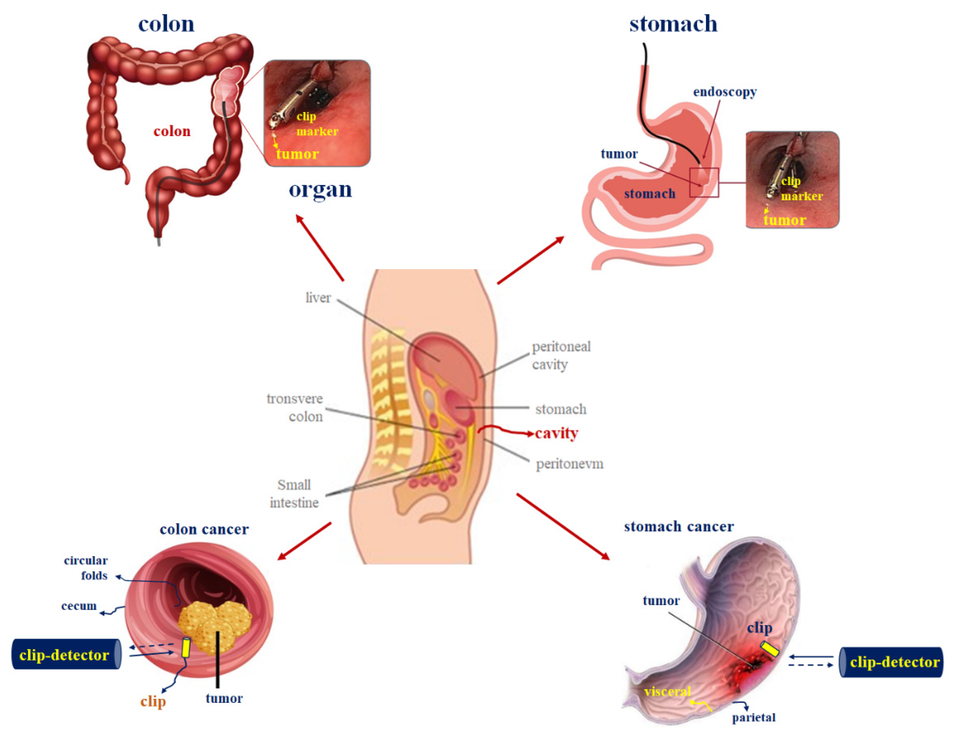
In laparoscopic surgery, it is difficult to locate malignant tumors for removal in the abdominal cavity [2]. In gastric cancer, malignant tumors exist in the visceral folds, as shown in Figure 1, and tumors in the colon exist in the inner mucosa, that is, in the circular folds. In laparoscopic surgery, it is difficult to locate the tumor surrounded by mucosal tissue in the cavity using a surgical instrument inserted using a trocar.
Therefore, when removing a tumor, medical accidents may occur due to incorrect excision [2]. In the case of gastric cancer, if a tumor existing in the visceral layer is found in the cavity, it becomes difficult to locate the tumor because of the parietal peritoneum. Furthermore, in the case of colorectal cancer, if a tumor existing in circular folds is found in the cavity, it becomes difficult to locate the tumor because of the cecum. Therefore, it is difficult to identify the extent of the incision in the parietal peritoneum or cecum for removing the tumor. To overcome these problems, the method of using a clip-detector during laparoscopic surgery is suitable.
In laparoscopic surgery, to extract a tumor using a clip-detector, a clip is installed using a stomach scope or colonoscope as shown in Figure 1. As shown in Figure 2, the clip is installed around the tumor, the endoscope is removed again, and laparoscopic surgery is initiated [2]. At this time, the sensor is inserted into the cavity using the trocar to locate the clip [2]. The sensor moves around a specific location in the parietal peritoneum or cecum. The sensor locates the clip installed around the tumor of visceral or circular folds and excises the tumor by making an incision at the location.
The underlying reason behind the ability of the detector in locating the clip installed around the tumor is that the magnetic coil is coupled around the clip and an induced magnetic field is generated against the eddy current. Furthermore, the source magnetic field is generated to induce a current, and the magnetic coil is wound at the end of the detector. When the source magnetic field and the induced magnetic field undergo magnetic coupling (as shown in Figure 3) and the resonant frequency is matched, an alarm is generated from the speaker connected to the detector. In this manner, the clip-detector can identify the location of the tumor.
2.2. Magnetic Coupling Analysis of Clip-Detection for Tumor Excision
To locate the clip, magnetic coupling must occur between the clip and detector. Therefore, it is necessary to analyze the characteristics of magnetic coupling. The clip-detector functions based on the inductive current method according to Biot–Savart and lens laws. Accordingly, the clip-detector can be designed using coil and ferrite material [15]. Thus, the magnetic field is generated by the magnetic induction method according to Biot–Savart law that is given by Equation (1).
where Iext is the excitation current, Δs is the infinitesimal of a coil, and θ and d are the phase response and transmission distance between the detector and metal (clip), respectively [15]. The eddy current (Ieddy) is generated in the metal (clip) when the magnetic field is excited at the coil; the magnetic field is changed by the excitation current (Iext) in the coil by Faraday’s law, and the excitation current is changed by the induced magnetic field (Heddy). Therefore, the induced magnetic field is generated by the magnetic coupling between the coil and metal (clip), wherein the magnetic field of coil is transferred to a metal (clip) as shown in Figure 4. The eddy current (emf) (expressed by Equation (2)) is generated in the metal (clip), as illustrated in Figure 4. The metal (clip)-detector operates when the coil frequency (fHext) and the metal (clip) frequency (fHeddy) are equal , where B is the magnetic flux density.
In general, the magnetic coupling method for wire transmission exhibits high efficiency (above 90%), and the energy of the magnetic field is efficiently transmitted to the tissue owing to the relative permeability of 1.0 [16,17].
The frequency and maximum current allowed in the human body according to the standard of KSC IEC 60479-2 and KSC IEC 61200-413 (children reference) are within 20 kHz and 20 mA, respectively [18,19]. For wireless energy transmission, the dual-loop, helical, and spiral coils are commonly used for magnetic coupling [20,21,22]. The helical coil of the clip-detector is used because of its suitable structure. Furthermore, the helical coil can be designed in a compact size, and it has a wide field distribution. In addition, the clip-detector with a helical-type coil can also suitably pass through the working channel of a trocar or endoscope.
The coil part and oscillation circuit are important. The coil consists of transmission (TX) and receiving (RX) parts. The oscillator is designed based on Colpitts circuit that has a high-quality factor (Q) owing to high capacitance. To increase Q, the quality factor is increased. Consequently, the frequency is increased. Therefore, the meta-detection performance is excellent. Moreover, the coil must be enveloped around the ferrite during the coil design, as shown in Figure 5. The coil turn number (N) is highly important in the metal (clip)-detection circuit, and copper coil is used.
At the TX part of ferrite and coil, the ferrite diameter and length are 22.4 mm, as shown in Figure 5. The diameter (tw), length (lcoil), and turn number (N) are 0.13 mm, 22 mm, and 50 turns, and the space (dh) between the coils and air capacitance (Ch) are 0.315 mm and 100 pF, respectively. Moreover, the inductance of coil is 10 mH. In the RX part of ferrite and coil, the ferrite diameter and length are 22 mm. The diameter (tw), length (lcoil), and turn number (N) are 0.12 mm, 18.6 mm, and 22 turns, and the space (dh) between the coils and air capacitance (Ch) is 0.206 mm and 68 pF, respectively. Moreover, the inductance of coil is 4.8 mH. A titanium clip (Olympus, Tokyo, Japan) is used, which features a diameter (Dc) and height (hc) of 2.5 mm and 11 mm, respectively (Figure 5). Then, the magnetic flux density is 2.2 μT.
3. Design and Fabrication
The proposed clip-detector is composed of TX and RX parts, as shown in Figure 6. From the figure, the TX part consists of TX coil, amplifier, feed band, resonant circuit, and bias voltage; and the RX part comprises RX coil, relay oscillator, amplifier, filter, speaker, and bias voltage. The TX part is operated by an oscillator. When voltage is supplied to the amplifier, the thermal noise increases. Subsequently, the noise passes through the feedback and enters the resonator. The resonator is selected for realizing resonant frequency amidst the noise (see Figure 6).
Figure 7 shows the schematic of the clip-detector circuit based on the metal (clip)-detection technique. As shown in the figure, the circuit is connected to the amplifier, speaker, two coils, and oscillator parts, and the coil (TX/RX) and capacitor (C8–C11) are parallel-structured and operated in the resonant circuit. The capacitors (C8–C11) play an important role in Colpitts circuit.
4. Experimental Results
4.1. Designed Circuit Simulation Results
The simulation results under the oscillation condition of the designed oscillator are shown in Figure 8. As shown in the figure, the oscillation condition can be divided into two types: start-up condition and steady-state condition. The start-up voltage is 2.5 V between 0 ns and 40 ns, and the steady-state oscillation voltage range is maintained as 0.0–5.7 V (output current and power of 2.3 mA and 5.75 mW) between 40 ns and 200 ns in the oscillation condition.
Figure 9 shows the simulation result for the sine waveform of an oscillation condition using the Colpitts oscillator. As shown in the figure, the sine waveform has an input voltage (Vin: ωeddy) and output voltage (Vout: ωHext).
For the input voltage (Vin: ωeddy) of 1 V, the output voltage (Vout: ωHext) is maintained as 2.6 V. If the oscillator starts operating, the steady-state oscillation voltage range is maintained from 0.0 V to 5.7 V between 40 ns and 200 ns under a sine waveform input voltage (Vin: ωeddy) of 1 V. However, if coupling occurs between the coil and the metal (clip) of the oscillator, the output voltage (Vout: ωHext) is maintained at 2.6 V (ωmetal-detection), as shown in Figure 10.
Therefore, the phase difference between the input voltage (Vin: ωeddy) of the oscillator and the coupling voltage (the coupling voltage between the oscillator and metal (clip)) is 90°, as shown in Figure 11. Therefore, the ωmetal-detection signal is detected at a phase difference of 90° between the frequency of the magnetic field (ωHext), generated by the oscillator coil and the induced magnetic field (ωHeddy) which is caused by the induced current generated in the metal (clip), and accordingly, metal (clip) detection occurs.
At this time, to perform the metal (clip) detection, the frequency of ωmetal-detection is matched between the peak point of ωHext and the negative peak point of ωHeddy, as shown in Equation (3).
For this reason, when ωHext is equal to ωHeddy, ωmetal-detection = 1, the function of metal (clip) detection is realized. If ωmetal-detection > 1 or ωmetal-detection < 1, the metal (clip-detector does not function because ωmetal-detection ≠ 1. Therefore, when ωmetal-detection = 1, the metal (clip) is detected as shown in Figure 12, and ωHext and ωHeddy are 90° in phase with respect to each other. At this time, ωmetal-detection is able to identify the location of tumors in the stomach or colon during laparoscopic surgery with a voltage of 2.77 V and a frequency of 11.335 kHz, with a duty cycle of 50%.
4.2. Animal Test and Measurement Results
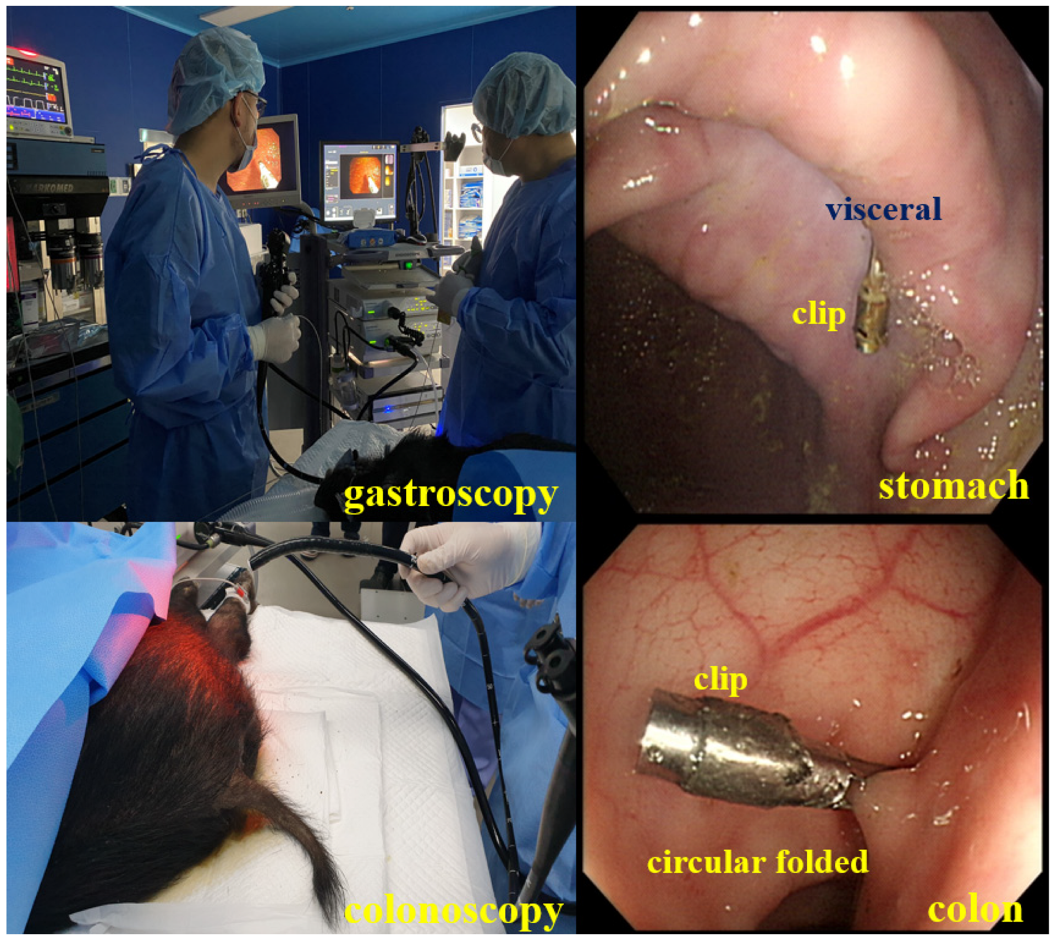
To test the performance of the designed clip-detector, we conducted animal experiments. The animal was tested at the experimental animal center of KNOTUS (Songdo Research Center, Incheon, Republic of Korea). We obtained institutional review board (IRB) permission from the animal ethics commission (KNOTUS-IACUC-20-KE617). In the animal test, a male farm mini pig (1 ea) weighing 40 kg was used. For animal experiments, the clip-detector installed four clips in the visceral: middle circular muscle layer of the stomach; and cecum: sigmoid colon using an endoscope or a colonoscope, as shown in Figure 13.
As shown in Figure 14, we checked whether the clip was installed correctly by the endoscope on an external monitor and prepared for laparoscopic surgery.
After installing the clip by endoscopy, we tested the detection performance of the clip in laparoscopic surgery, as shown in Figure 15a. The detector was inserted into the abdominal cavity through the trocar, and the detector started to detect the clip in the cavity as shown in Figure 15b. When the clip existing in the stomach (visceral) and the colon (circular folds) was detected, the detector generated an amplitude of 2.27 V (@ 11.33 kHz, output power of 5.52 mW), as shown in Figure 15c, and an alarm was generated from the speaker. Upon encountering the clip, the detector is coupled to the clip; the detection time was 1.12 s and 1.20 s (investigation time of 2.21 s and 3.6 s). Here, 1.12 s and 1.20 s are the detection times when the detector is coupled with the clip in the stomach and colon, and 2.21 s and 3.6 s are the time consumed to determine the clip position of the stomach and colon in the cavity. It can be confirmed that there is no time delay and that the response time for detecting a tumor is exceedingly short.
The thickness of the gastric mucosa between the clip and the detector is mostly 2 cm, and the colon is 1 cm. The detector was separated by a distance of 0.5 cm from the parietal peritoneum above. Furthermore, in the colon, the detector was approximately 0.5 cm away from the cecum. Therefore, the distance at which the detector detects the clip is at the level of 2.5 cm (top) and 1.5 cm (colon).
After the designed detector is docked to the trocar and inserted into the cavity, the time it takes for the clip-detector to determine the tumor location of the stomach and colon is recorded as 2.21 s and 3.6 s, respectively. In addition, the module for detecting the tumor location is inserted into the clip as shown in [9,10,13], and is designed to be integrated. Connection of the detection module to the clip without using a wire is advantageous. Therefore, the error in the determination of the clip position is minimized. Following the same logic, there will be an error equivalent to the wire length in the position of the clip with wire [11,12,14]. However, because the designed clip can be directly connected, the error in the clip position determination can be reduced. In addition, the proposed clip-detector has the ability of determining the tumor location for both the stomach and colon, as in [9,13]. In the studies conducted by Choi et al. and Yoshida et al. [9,13], the clip positions were determined for both the stomach and colon simultaneously. Nonetheless, it is highly important that the clip-detector be capable of locating the tumor accurately and speedily.
Table 1 compares the tumor detection capability of the previously studied detector and the designed detector, and the time it consumes to locate the tumor.
The designed detector is analyzed to be 0.08 times (for stomach) and 0.12 times (for colon) faster than the detector proposed by Yoshida et al. [13] in locating the tumor. In the course of animal experiments, using a detector to determine the position of the clip, it was found directly through the surgeon’s operation. Before finding the position of the clip, the surgeon used a detector to find the position of the clip without knowing the position of the clip. At this time, the time taken to find the position of the clip using the detector was 2.21 s in the stomach and 3.6 s in the colon. Therefore, the clip-detector in this study is better than that proposed by Yoshida et al. [13].
If N clips are used, magnetic coupling interference may occur depending on the spacing between the clips. In other words, if the distance (d) between clips becomes longer, the magnetic field intensity is attenuated (α: attenuation of magnetic field intensity) by the distance (d2) as shown in Equation (4), and interference can be reduced. However, if the spacing between the clips becomes narrower, the magnetic field intensity increases by the distance (d2), which may lead to greater interference [23].
In the course of animal experiments, we attached only one clip when attaching the clip to the stomach or colon as shown in Figure 16. In addition, we use the detector to find one clip position. So, there was no interference problem. However, the problem of interference between clips seems to have to be tested by increasing the number of clips. Therefore, we plan to test for interference by increasing the number of clips in the future. If there is an interference problem, we plan to solve it through additional research.
Additionally, since the detector for detecting the clip is a magnetic field component induced by the coil, it has been confirmed that it does not interfere with the surrounding forceps.
Finally, the method of this study is 2.27 V (5.52 mW/2.2 μT) at 11.33 kHz. That is, our method uses a magnetic field with a very weak strength, so it is analyzed that there is no adverse effect on the human body. That is, the voltage, power, and magnetic flux density generated by the detector to detect the last clip are 2.27 V, 5.52 mW, and 2.2 μT (@ 11.33–11.335 kHz), respectively. In the recommendations of ICNIRP, the republic of Korea recommends that the exposure limit of human electromagnetic waves be within the range of 3.0–150 kHz, with a voltage of 87 V or less and 5 A/m (magnetic flux density: 6.25 μT) [23,24]. Therefore, the proposed detector is analyzed to have no adverse effect on the human body in detecting the clip. In addition, since the medical magnetic field used for human diagnosis and treatment is harmless to the human body, most studies have been conducted for the application of MRI, magnetic field therapy, capillary circulation state examination, and a capsule endoscopy diagnostic kit [25,26,27,28]. Of course, if a high-density, strong pulsed magnetic field (more than 100 μT) is used (even for a short time), it stimulates the nervous system, reduces blood volume, and causes muscle pain due to muscle stiffness [24,29,30].
Furthermore, the clip used for endoscopy was originally developed and used for hemostasis and puncture closure [8]. For many researchers or surgeons, the time to attach one clip (within 1 min) is very short. However, standard methods, such as the India ink tattooing method and the self-blood injection therapy method, inject in four directions [31,32]. Additionally, this method is time consuming because it uses two endoscopic syringes. Because the clip is used for perforation, it usually remains mounted within the organ for 5–7 days (or even years) after the clip is placed. However, safety is not an issue as most of them are excreted through the bowels.
When the operation is finished, the clip is delivered to the pathology department along with the lesion. Therefore, there is no need to separately remove the clip.
5. Conclusions
This paper presents a detection method of malignant tumor in the stomach and colon during laparoscopic cancer surgery. Determining the extent of excision for gastric and colon malignancy in the cavity is difficult. Nonetheless, after installing the clip around the tumor, the method of locating the clip using a detector and extracting the tumor is effective.
Because the proposed clip-detector uses magnetic field coupling based on metal (clip)-detection technology, tissue penetration is easy. Furthermore, the amplitude of magnetic coupling has a relatively high gain at 2.27 V (@11.33 kHz). Therefore, if the detector detects the clip installed in the tumor, an alarm is generated from the speaker at 2.27 V (frequency: 11.33 kHz). In this manner, it is possible to speedily locate the tumor based on the alarm sound in the operating room.
The designed clip detection method has no such side effects as the conventional ink tattoo method, indocyanine green fluorescence staining method, and autologous blood maker method, and it can speedily locate the tumor, reducing the burden on surgeons and patients. Because the clip-detector uses ferrite and coil, it is inexpensive and easy to manufacture. Furthermore, the clip-detector using ferrite and coil can be mass-produced owing to the low unit price. Because the clip-detector uses an endoscope, it is expected that this study will not only enable efficient surgical laparoscopic surgery, but also stimulate the endoscopy-specific medicine market in the future.
Author Contributions
Design and simulation; K.Y., analysis and supervisor; K.G.K. and J.-W.C. All authors have read and agreed to the published version of the manuscript.
Funding
This research was supported by the Ministry of Science and ICT (MSIT), Korea, under the Information Technology Research Center (ITRC) support program (IITP-2021-2017-0-01630) supervised by the Institute for Information and communications Technology Promotion (IITP), G-ABC FRD2019-11-02(3), and by the research was supported by Basic Science Research Program through the National Research Foundation of Korea (NRF) funded (NRF-2020R1F1A1076839).
Institutional Review Board Statement
The experiment was an animal test from the “experimental animal center of KNOTUS (Songdo Research Center, Incheon, Republic of Korea)” KNOTUS-IACUC-20-KE617 through the permission of animal institutional review board (IRB) at animal ethics commission on approval of 5 November 2020.
Informed Consent Statement
Not applicable.
Data Availability Statement
The data presented in this study are available upon request from the permission corresponding author. The data are not publicly available because of privacy and ethical restrictions.
Acknowledgments
Kwang Gi Kim and Jun-Won Chung equally contributed to the work. Kwang Gi Kim and Jun-Won Chung are the co-corresponding authors. This research and animal test was supported by the Scaleup Challenge Lab at Inha University.
Conflicts of Interest
The authors declare no conflict of interest. The funders had no role in the design of the study; in the collection, analyses, or interpretation of data; in the writing of the manuscript, or in the decision to publish the results.
References
- World Cancer Research Fund International. Colorectal Cancer Statistics. Available online: www.wcrf.org/cancer-trends/colorectal-cancer-statistics (accessed on 21 March 2021).
- Morgan, E.; Arnold, M.; Camargo, M.C.; Gini, A.; Kunzmann, A.T.; Matsuda, T.; Meheus, F.; Verhoeven, R.H.; Vignat, J.; Laversanne, M.; et al. The current and future incidence and mortality of gastric cancer in 185 countries, 2020–40: A population-based modelling study. eClinicalMedicine 2022, 47, 101404. [Google Scholar] [CrossRef]
- Zarif, T.E.; Yibirin, M.; Oliveira-Gomes, D.D.; Machaalani, M.; Rashad, N.; Bittar, G.; Bahmad, H.F.; Bitar, N. Overcoming therapy resistance in colon cancer by drug repurposing. Cancers 2022, 14, 2105. [Google Scholar] [CrossRef]
- Luigiano, C.; Ferrara, F.; Morace, C.; Mangiavillano, B.; Fabbri, C.; Cennamo, V.; Bassi, M.; Virgilia, C.; Consolo, P. Endoscopic tattooing of gastrointestinal and pancreatic lesions. Adv. Ther. 2012, 29, 864–873. [Google Scholar] [CrossRef]
- Jeong, O.; Cho, S.B.; Joo, Y.E.; Ryu, S.Y.; Park, Y.K. Novel technique for intraoperative tumor localization during totally laparoscopic distal gastrectomy: Endoscopic autologous blood tattooing. Surg. Endosc. 2012, 26, 1778–1783. [Google Scholar] [CrossRef]
- Trakarnsanga, A.; Akaraviputh, T. Endoscopic tattooing of colorectal lesions: Is it a risk–free procedure? World J. Gastrointest. Endosc. 2011, 3, 256–260. [Google Scholar] [CrossRef]
- Bințințana, V.; Calboreanb, A.; Mocanf, M.; Macaveib, S.; Cordoș, A.; Ciucea, C.; Bințințana, A.; Chiraa, R.; Nagya, G.; Surlinc, V.; et al. New inductive proximity sensor platform for precise localization of small colorectal tumors. Mater. Sci. Eng. C 2020, 106, 110146. [Google Scholar] [CrossRef]
- Kim, E.J.; Chung, J.W.; Kim, S.Y.; Kim, J.H.; Kim, Y.J.; Kim, K.O.; Kwon, K.A.; Park, D.K.; Choi, D.J.; Park, S.W.; et al. Autologous blood, a novel agent for preoperative colonic localization: A safety and efficacy comparison study. Surg. Endosc. 2019, 33, 1080–1086. [Google Scholar] [CrossRef]
- Choi, W.J.; Moon, J.H.; Min, J.S.; Song, Y.K.; Lee, S.A.; Ahn, J.W.; Lee, S.H.; Jung, H.C. Real–time detection system for tumor localization during minimally invasive surgery for gastric and colon cancer removal: In vivo feasibility study in a swine model. J. Surg. Oncol. 2017, 117, 699–706. [Google Scholar] [CrossRef]
- Kojima, F.; Sato, T.; Tsunoda, S.; Takahata, H.; Hamaji, M.; Komatsu, T.; Okada, M.; Sugiura, T.; Oshiro, O.; Sakai, Y.; et al. Development of a novel marking system for laparoscopic gastrectomy using endoclips with radio frequency identifcation tags: Feasibility study in a canine model. Surg. Endosc. 2014, 28, 2752–2759. [Google Scholar] [CrossRef]
- Matsuzaki, I.; Hattori, M.; Yamauchi, H.; Goto, N.; Iwata, Y.; Yokoi, T.; Tsunemi, M.; Kobayashi, M.; Yamamura, T.; Miyahara, R. Magnetic anchor–guided endoscopic submucosal dissection for colorectal tumors (with video). Surg. Endosc. 2020, 34, 1012–1018. [Google Scholar] [CrossRef]
- Ohdaira, T.; Nagai, H. Intraoperative localization of early–stage upper gastrointestinal tumors using a magnetic marking clip–detecting system. Surg. Endosc. 2007, 21, 810–815. [Google Scholar] [CrossRef]
- Yoshida, A.; Kurumi, H.; Ikebuchi, Y.; Kawaguchi, K.; Yashima, K.; Kamitani, Y.; Yasui, S.; Nakada, Y.; Kanda, T.; Takata, T.; et al. New closure method using loop and open–close clips after endoscopic submucosal dissection of stomach and colon lesions. Clin. Med. 2021, 10, 3260. [Google Scholar] [CrossRef]
- Calborean, A.; Macavei, S.; Mocan, M.; Ciuce, C.; Cordos, A.; Bintintan, A.; Chira, R.; Pestean, C.; Pop, O.; Barbu–Tudoran, L.; et al. Laparoscopic compatible device incorporating inductive proximity sensors for precise detection of gastric and colorectal small tumors. Surg. Oncol. 2020, 35, 504–514. [Google Scholar] [CrossRef]
- Ryu, D. Performance measurement of the wireless charging devices using electromagnetic induction techniques. J. Korea Navig. Inst. 2015, 19, 237–243. [Google Scholar]
- Kurs, A.; Karakis, A.; Moffatt, R.; Fisher, J.P.; Soljacic, M. Wireless power transmission via strongly coupled magnetic resonance. Science 2007, 317, 83–86. [Google Scholar] [CrossRef] [Green Version]
- Pethig, R.; Kell, D.B. The passive electrical properties of biological systems: Their significance in physiology, biophysics and biotechnology. Phys. Med. Biol. 1987, 32, 933. [Google Scholar] [CrossRef] [Green Version]
- Choi, J.; Jeong, B. Characteristic analysis of magnetic resonance coils for wireless power transfer. In Proceedings of the KIEE Summer Annual Conference; The Korean Institute of Electrical Engineers: Seoul, Korea, 2015; p. 15. [Google Scholar]
- Gabriel, S.; Lau, R.W.; Gabriel, C. The dielectric properties of biological tissue: Part III–parametric models for the dielectric spectrum of tissues. Phys. Med. Biol. 1996, 41, 2271–2293. [Google Scholar] [CrossRef] [Green Version]
- Ju, Y.J. Magnetic–Resonance Wireless Power Transfer System and Its EMF Safety at 100 kHz Band. Ph.D. Thesis, Dankook University, Yongin-si, Korea, 2012. [Google Scholar]
- Cheon, S.; Kim, Y.H.; Kang, S.Y.; Lee, M.L.; Lee, J.M.; Zyung, T. Circuit–model–based analysis of a wireless energy–transfer system via coupled magnetic resonances. IEEE Trans. Ind. Electron. 2011, 58, 2906–2914. [Google Scholar] [CrossRef]
- Jang, Y.; Kwon, J.; Park, J.; Choi, J. Design of a high efficiency resonator for wireless power transfer. J. Korean Inst. Electromagn. Eng. Sci. 2011, 22, 820–826. [Google Scholar] [CrossRef] [Green Version]
- Rappaport, T.S.; MacCartney, G.R.; Samimi, M.K.; Sun, S. Wideband millimeter-wave propagation measurements and channel models for future wireless communication system design (Invited Paper). IEEE Trans. Commun. 2015, 63, 3029–3056. [Google Scholar] [CrossRef]
- ICNIRP. ICNIRP Guidelines for limiting exposure to time-varying electric, magnetic and electromagnetic fields. Health Phys. 1998, 74, 494–522. [Google Scholar]
- WHO. Electromagnetic Fields and Public Health; WHO Factsheet; WHO: Geneva, Switzerland, 2007; p. 322. [Google Scholar]
- Antonios, T.F.; Singer, D.R.; Markandu, N.D.; Mortimer, P.S.; MacGregor, G.A. Structural skin capillary rarefaction in essential hypertension. Hypertension 1999, 33, 998–1001. [Google Scholar] [CrossRef] [Green Version]
- Park, B.J.; Kim, M.G.; Suh, S.I.; Hong, S.J.; Cho, K.R.; Seo, B.K.; Lee, K.Y.; Lee, N.J.; Kim, J.H. The usefulness of test bolus examination in three dimensional contrast enhanced MR angiography of the carotid artery. J. Korean Med. 2001, 44, 317–323. [Google Scholar] [CrossRef]
- Howard, R.; Mertz, M.D. Fecal incontinence: Evaluation and treatment. Gastroenterol. Clin. N. Am. 2003, 32, 685–706. [Google Scholar]
- Szulim, P.; Gontarz, S. Extraction of magnetic field features to determine the degree of material strain. Materials 2021, 14, 1576. [Google Scholar] [CrossRef]
- Moon, C.B.; Lee, H.Y.; Kim, B.M.; Shin, Y.S. Left ventricle segmentation algorithm through radial threshold determination on cardiac MRI. J. KIISE 2009, 36, 825–834. [Google Scholar]
- Lövsund, P.; Öberg, P.Å.; Nilsson, S.E.G.; Reuter, T. Magnetophosphenes: A quantitative analysis of thresholds. Med. Bio-Log. Eng. Comput. 1986, 18, 326–334. [Google Scholar] [CrossRef]
- Available online: https://mail.google.com/mail/u/1/#inbox/CllgCHrdlLkkKgcmPDvJRPnDPBRKNxTnqllkckMVhFhhjlxgpRtQlSdwggVxXdhSXGwRsdRhMGq?projector=1 (accessed on 22 March 2021).
Figure 1.
Schematic of the use of clip-detector.

Figure 2.
Flowchart of clip detection and tumor localization.

Figure 3.
Coupling between clip and detector.

Figure 4.
Schematic of magnetic coupling between the clip and detector.

Figure 5.
Number and structure of coil turns for clip design.

Figure 6.
Block diagram of the clip-detector.

Figure 7.
(a) Clip-detector circuit and (b) 3D-printed clip-detector photograph.

Figure 8.
Simulation result under the oscillation condition for Colpitts oscillator.

Figure 9.
Simulation result of the sine waveform for the Colpitts oscillator and metal (clip).

Figure 10.
Simulation result of the sine waveform with metal (clip) detection for Colpitts oscillator and metal clip.
Figure 10.
Simulation result of the sine waveform with metal (clip) detection for Colpitts oscillator and metal clip.

Figure 11.
Simulation result of the phase difference between Colpitts oscillator and metal (clip).

Figure 12.
Simulation result of the metal (clip) detected using pulse signal.

Figure 13.
Process of clip installation in mucosa in stomach and colon using endoscope and colonoscope, respectively.
Figure 13.
Process of clip installation in mucosa in stomach and colon using endoscope and colonoscope, respectively.

Figure 14.
Clip set installed in the mucosa of colon and stomach using colonoscope and endoscope, respectively.
Figure 14.
Clip set installed in the mucosa of colon and stomach using colonoscope and endoscope, respectively.

Figure 15.
Animal test of the developed clip-detector: (a) laparoscope surgery (b) clip detection (c) clip detected signal.
Figure 15.
Animal test of the developed clip-detector: (a) laparoscope surgery (b) clip detection (c) clip detected signal.

Figure 16.
Method of removal and suturing after attaching the clip to the lesion site.


Table 1.
Comparison of the detection time of clip location of the designed clip-detector and others reported previously.
Table 1.
Comparison of the detection time of clip location of the designed clip-detector and others reported previously.
| Ref [#] | Detection Time of Tumor [s] | Methods | |
|---|---|---|---|
| Stomach | Colon | ||
| this work | 2.21 | 3.60 | ferrite and coil |
| [9] | 40.5 | 38.4 | RFID |
| [10] | 25.0 | - | RFID |
| [11] | - | 8.0 | magnet |
| [12] | - | 5.7 | magnet |
| [13] | 24.9 | 18.7 | open–close clip closure method |
| [14] | - | 15 to 90 | magnet |
foot note: # symbolizes the reference number.
Publisher’s Note: MDPI stays neutral with regard to jurisdictional claims in published maps and institutional affiliations. |
© 2022 by the authors. Licensee MDPI, Basel, Switzerland. This article is an open access article distributed under the terms and conditions of the Creative Commons Attribution (CC BY) license (https://creativecommons.org/licenses/by/4.0/).
Share and Cite
MDPI and ACS Style
Yoon, K.; Chung, J.-W.; Kim, K.G. A Metal Detector for Clip Location Tracking of Stomach and Colon Cancer during Laparoscopic Surgery. Appl. Sci. 2022, 12, 7330. https://doi.org/10.3390/app12147330
AMA Style
Yoon K, Chung J-W, Kim KG. A Metal Detector for Clip Location Tracking of Stomach and Colon Cancer during Laparoscopic Surgery. Applied Sciences. 2022; 12(14):7330. https://doi.org/10.3390/app12147330
Chicago/Turabian StyleYoon, Kicheol, Jun-Won Chung, and Kwang Gi Kim. 2022. "A Metal Detector for Clip Location Tracking of Stomach and Colon Cancer during Laparoscopic Surgery" Applied Sciences 12, no. 14: 7330. https://doi.org/10.3390/app12147330
Note that from the first issue of 2016, this journal uses article numbers instead of page numbers. See further details here.