
Mixed Mode I/II Fracture Analysis of Bi-Material Adhesive Bonded Joints Using a Novel Short Beam Specimen


1
Welding and Joining Research Center, School of Industrial Engineering, Iran University of Science and Technology (IUST), Tehran 16846-13114, Iran
2
Department of Aerospace, Physics and Space Sciences, Florida Institute of Technology, Melbourne, FL 32901, USA
*
Author to whom correspondence should be addressed.
Appl. Sci. 2021, 11(11), 5232; https://doi.org/10.3390/app11115232
Submission received: 29 April 2021
/
Revised: 28 May 2021
/
Accepted: 30 May 2021
/
Published: 4 June 2021
(This article belongs to the Special Issue Mechanical Properties and Characterization of Bonded Composites)
Abstract
:Until now, some test specimens with different shapes and loading mechanisms have been utilized for investigating the cracking behavior of adhesive bounded joints. In this research, using a novel test configuration called adhesive short bend beam specimen containing an inclined crack and loaded by three-point bending, mixed mode I/II fracture parameters of a crack initiated in the adhesive part is studied. Compared to other test methods, the specimen used in this research needs a lesser amount of material and the fracture test can be performed easily. A large number of finite element models of this specimen were analyzed using ABAQUS code to study the effect of adhesive and adherent type, and also the crack length and loading span distance on KI, KII, T-stress and fracture initiation direction under different mode mixities. The results showed that the fracture parameters (and in particular the shear mode component) are sensitive to the type and location of adherent in the bounded joint; however, the shape and size of fracture plastic zone is not affected noticeably by the type of adhesive-adherent materials. It was also shown that the complete mode mixities ranging from pure mode I to pure mode II can be introduced for adhesive bounded joints using the proposed test specimen and therefore the specimen is a good candidate test configuration for investigating the mixed mode I/II fracture behavior of adhesive bounded joints.
1. Introduction
Joining of structural and engineering parts with adhesive has always been of particular interest in many high-tech and modern components and industries such as aerospace, civil and automotive engineering. This is because the advantages and benefits of such a joining method compared to conventional techniques such as welding. By developing and manufacturing high strength and high resistance adhesives capable of working at elevated or low temperatures, adhesively bounded joints have received a good reputation in manufacturing advanced products due to their benefits such as high strength, fatigue and stiffness, low cost and low weight, and ability to join both similar and dissimilar parts [1]. However, lack of perfect bounding between the adhesive and adherent part and initiation of flaws, micro cracks and discontinuities inside the adhesive can significantly reduce the strength and load bearing capacity of adhesive bonded joints. Indeed, such discontinuities can increase the risk of failure of component from the bounding zone. In particular, some of the structural adhesives may behave as brittle material after curing and during life service. Such adhesive bounded joints are more vulnerable to sudden fracture in the presence of structural defects. Therefore, understanding the failure and crack growth mechanism in these joints is necessary for reliable usage of adhesive bounded components in practical applications.
Interfacial fracture can be investigated via employing the framework of fracture mechanics in which the intensity of stress/strain field is defined by some parameters such as stress intensity factor and the fracture energy. The critical values of such parameters are often considered as mechanical properties characterizing the fracture behavior of adhesive bounded joints. Some experimental methods and testing specimens have been used in several studies to evaluate the load bearing capacity or fracture energy of such components. For example, double cantilever beam (DCB) and tapered double cantilever beam (TDCB) [2,3] are two well-known test configurations for tensile type or mode I fracture study of adhesive bounded joints. For mode II fracture study of such components there are some testing methods and specimens including edge notch flexural (ENF) [4] and end-loaded split (ELS) [5] that have been widely used by several researchers to measure the shear type fracture energy. However, in practice adhesive bounded joints can be subjected to complex state of loads and deformations. This loading situation may result in mixed mode tensile-shear (i.e., mixed mode I/II) fracture phenomenon in adhesive bounded joints. Thus, some other test samples have been proposed for evaluating and studying the mixed mode I/II fracture in these components. The asymmetric DCB and asymmetric TDCB specimens proposed by Xiao et al. [6] and Park and Dillard [7], respectively are modified forms of DCB and TDCB samples which can produce mixed mode I/II (but limited range of mode mixities) in addition to the pure mode I case in adhesive bounded joints. Other test configurations such as mixed mode bending (MMB) [8], single leg bending (SLB) [9] and semi-circular bend (SCB) [10] specimens were also employed by some researchers for fracture study of adhesive bounded joints.
However, the aforementioned testing methods have some shortcomings and difficulties such as lack of ability for introducing the full range of mode mixities, requirement of complex testing fixtures and rigs for conducting the experiments, large size of test specimen, etc. Therefore, designing and proposing new and suitable testing methods for investigation mixed mode I/II fracture behavior of adhesive bounded joints is still a necessary and interesting subject. Hence, in this research, a simple and new test method and geometry is proposed for analyzing the behavior of adhesive bounded joints that can easily produce the complete ratios of mode I over mode II by a conventional three-point bending fixture. In the next sections of this paper, after describing the proposed test sample, its fracture parameters are determined for a wide range of geometrical, loading and material parameters, including the modes I and II stress intensity factors and T-stress. It is shown that due to some advantages, the proposed testing configuration can be considered as a good and favorite candidate test method for investigating the fracture behavior of adhesive bounded joints.
2. Proposed Mixed Mode I/II Test Specimen for Adhesive Bounded Joints
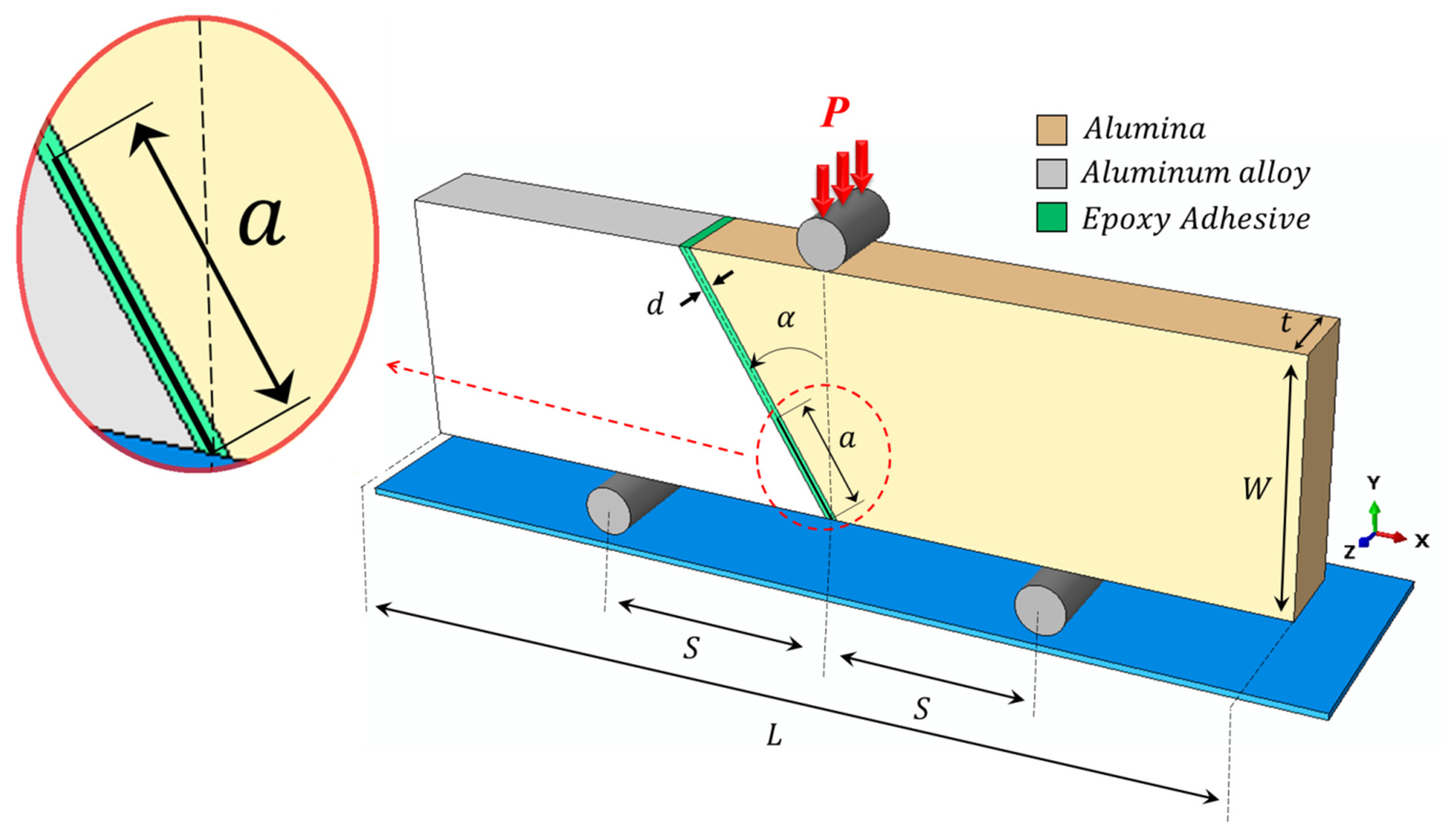
Figure 1 shows the bi-material test configuration proposed herein for investigating the mixed mode I/II fracture in adhesive joints. The specimen is called bi-material inclined notch short bend beam (BISBB). Two parts that are attached by an adhesive material create a rectangular shape as the overall configuration of the BISBB specimen with length L and width W. The width of adhesive is d and an edge crack with length a is assumed to be introduced in the middle of adhesive material. The specimen is loaded using a conventional three-point bend loading fixture in which the loading support distance is 2S. The state of mode I and mode II mixities can be changed in this specimen by inclining the interface or adhesive plane with respect to the upper loading direction shown by α angle in Figure 1. Indeed, by increasing the angle α from zero, the contribution of mode II or in-plane sliding deformation in the failure behavior of bi-material assembly increases and therefore the footprint of both crack opening and crack in-plane sliding deformations can be seen in the failure process of bi-material specimen joined by the adhesive material. Compared to many of the previously used adhesive bounded joints, the proposed BISBB specimen has a very simple geometry and testing setup and requires very little amount and size of adhesive and the adherent materials. The short beam like specimen containing inclined crack and loaded by symmetric three-point bend loading was investigated recently by Aliha and coworkers [11,12,13,14,15,16,17,18,19] for assessing mixed mode I/II fracture of different materials. The state of stress in the vicinity of crack tip in the short bend beam specimen can be influenced by the geometrical and loading parameters (such as crack length (a), crack inclination angle (α) and the loading span (2S)).
The left and right materials creating the BISBB specimen can be either similar or dissimilar. Here, alumina ceramic and aluminum metal alloy (Al) were considered for joining by an epoxy adhesive material to manufacture the proposed BISBB specimen. Table 1 illustrates the mechanical properties of the selected materials.
According to Williams [21], the polar stress fields in the vicinity of crack tip can be written as:
where r and θ are the crack tip coordinate located at the crack tip, and KI and KII are related to the singular terms of in this series expansion are the stress intensity factors. The first higher order term is T-stress which is constant and independent from the crack tip distance. O (r0.5) describes the higher order terms. According to the well-known literature [22,23,24,25], knowing these three fracture parameters (i.e., KI, KII and T) is sufficient for describing the crack tip stress/strain field and evaluating the failure behavior of cracked components subjected to mixed mode I/II loading. These fracture parameters depend on the geometry and loading conditions of any given test specimen. For the BISBB specimen, KI, KII and T can be written as:
in which YI, YII and T* are the geometry factors corresponding to KI, KII and T, respectively. These geometry factors are functions of crack length ratio (a/W), loading span ratio (S/W) and crack inclination angle (α) in the BISBB specimen. In order to use the BISBB specimen in fracture analysis of adhesive bounded joints and testing real cracked adhesive bounded joint materials, it is necessary to first determine these three fracture parameters. Since such parameters have not been reported in the literature for the BISBB specimen, the main aim of this research is to determine these three fracture parameters for the BISBB and investigate the influence of affecting parameters (such crack length ratio, loading span ratio and adherent types) on the variations of the fracture parameters. While there is no analytical solution available for determining the stress/strain field ahead of the crack tip in the BISBB specimen and extracting its fracture parameters (i.e., KI, KII and T), numerical analyses such as finite element method provide powerful tools for this issue that can be used for any desired fracture specimen. In the next section, the finite element method is utilized for computing the geometry factors of the BISBB specimen.
3. Numerical Analyses and Results
A finite element (FE) model of BISBB sample was created in the ABAQUS software. The overall dimensions of the specimen were: L = 54 mm, W = 15 mm, t = 5 mm and d = 0.4 mm. The crack length (a), loading span (S) and crack inclination angle (α) were considered as variables. Figure 2 shows the mesh patterns of adherent and adhesive parts and the crack tip region in the modeled BISBB specimen. A total number of 4600 CPE8 (i.e., 8-node biquadratic plane strain quadrilateral) elements were used for simulating the finite element model of specimen. In order to investigate the influence of adherent type on the fracture parameters, four permutations for modeling the left and right materials in the BISBB specimen were considered as (Aluminum- Adhesive- Alumina, Alumina- Adhesive- Aluminum, Aluminum- Adhesive- Aluminum, and Alumina- Adhesive- Alumina) as shown in Figure 3a–d, respectively. A vertical reference load P = 100 N was applied to the created finite element models and the mechanical properties of each part given in Table 1 were assigned to the models. Due to high stresses induced in the crack tip and also between the interface of adhesive and adherents, very fine elements and meshes were utilized. Using the J-integral method built in the ABAQUS code, the fracture parameters were determined for different a/W, S/W and α values.
Figure 4 and Figure 5 show the variations of mode I and mode II geometry factors (YI and YII) with crack inclination angle (α) for different a/W and S/W values. It is seen that by increasing the crack angle relative to the vertical direction, the contribution of mode I decreases and conversely mode II component increases. Indeed, the SIF ratio (KI/KII) approaches zero showing switching the state of crack tip deformation from pure opening tensile mode (for α = 0° in which YII = 0) towards pure shear and in plane sliding mode (i.e., YI = 0) at higher crack inclination angles. It is obvious from Figure 4 and Figure 5 that the magnitudes of both mode I and mode II geometry factors increase by increasing the crack length ratio and loading support distance ratio. The maximum value of YI occurs at α = 0° but a maximum of YII is seen typically at α = 10°. The highest sensitivity of mode I geometry factor (YI) and mode II geometry factor (YII) to the crack length ratio and span ratio (a/W and S/W) is seen at maximum values of geometry factors (i.e., α = 0° for mode I geometry factor and α = 10° for mode II geometry factor). For both geometry factors it is seen also from Figure 4 and Figure 5 that the sensitivity of data to a/W and S/W becomes smaller by increasing the crack inclination angle. Although pure mode I condition occurs at α = 0° for any desired a/W and S/W ratios, the corresponding condition for pure mode loading depends on the geometrical parameters, loading conditions and adherent materials. The corresponding value of mode II crack inclination angle (αII) determined from the finite element analyses of the BISBB specimen is listed in Table 2. According to this Table, for any given ratios of a/W and S/W, pure mode II crack angle varies typically between 30° and 55°. This angle decreases by increasing a/W ratio.
A parameter called mixity parameter, defined as , is used herein for assessment of the fraction and contribution of both modes I and II on fracture behavior of the BISBB specimen. Variations of geometry factors with Me are also presented in Figure 6. This Figure shows that complete ranges of mode mixities from pure mode I to pure mode II (i.e., ) can be achieved by the BISBB specimen. In this Figure, Me = 1 corresponds to pure mode I and Me = 0 shows the pure mode II loading conditions. This means that for the crack tip deformation of the BISBB specimen is controlled by dominantly shear mode (or mode II). On the contrary, when the mode mixity parameter (Me) varies from 1 to 0.5, the state of mixed mode I/II stress field for the BISBB specimen is mainly governed by the tensile type or opening mode I fracture mechanism. At Me = 0.5 that both YI and YII components are the same and equal together, a transition between dominantly tensile and dominantly shear mechanisms occurs. This situation for the BISBB specimen is achieved typically at crack inclination angles 25° < α < 35°, depending on the adherent types, their permutations, crack length and especially the loading span distances. This angle generally increases by increasing a/W and S/W. Figure 7 also presents the corresponding values of geometry factors under pure mode I and pure mode II loading conditions. As expected, the corresponding values of YI and YII at pure modes I and II conditions become greater by increasing the crack length ratio. Furthermore, for any given a/W value, mode I geometry factor increases by increasing the loading span and conversely mode II geometry factor decreases for longer bottom loading span distances. Also, according to Figure 6, mode II geometry factor is less sensitive to the crack length ratio a/W compared to the Mode I geometry factor for Me < 0.5.
The variations of non-dimensional T-stress (T*) for different loading conditions and material groups of the analyzed BISBB samples are presented in Figure 8. As seen, the T-stress is significantly negative for mode I dominant conditions (i.e., smaller values of α). Under such situations the value of T* is sensitive to the crack length ratio (a/W). However, by further increasing the crack angle and moving towards pure mode II loading condition, the sensitivity of T-stress to a/W becomes lesser and the corresponding value of T* tends to zero. The absolute value of T* increases in the BISBB specimen by increasing the crack length ratio (a/W) and loading span ratio (S/W). Based on the fracture mechanics literature for bonded components, the non-singular term can play a significant role on mixed mode I/II fracture if the magnitude of T-stress is high enough compared to the singular terms [26,27,28,29,30]. A parameter called Biaxiality ratio (Bi) defined as is a suitable measure for comparing the importance of T-stress relative to the stress intensity factors (KI and KII). The variations of this parameter for the analyzed BISBB specimens have been illustrated in Figure 9 for different a/W and S/W and α values. Under dominantly mode I loading conditions (i.e., α < 20°), the value of Bi is significantly negative and its magnitude increases by increasing the crack length ratio (a/W). This reveals that the non-singular stress term (T-stress) has significant role on the process of dominantly pure mode I brittle fracture of the BISBB specimen. Compared to previously used test samples for investigating mixed mode I/II (such as asymmetric semi-circular bend, four-point bend, Brazilian disc, diagonally square plate, edge crack triangular specimen), the magnitude of Bi parameter is significantly high [31,32,33,34,35,36]. This shows that the effect of T-stress in the fracture process of BISBB specimen is more pronounced than the other mixed mode samples [32,33,34,35,36,37,38,39]. However, by moving towards pure mode II loading condition the magnitude of Bi parameter reduces showing the non-significant influence of T-stress on the fracture of this specimen. The absolute value of Biaxiality ratio parameter increases by increasing the crack length ratio and loading span ratio for smaller crack inclination angles (α < 30°) and conversely its magnitude reduces by increasing a/W and S/W for α > 30°.
It should be noted that the single-material and homogenous short bend beam specimen was analyzed in previous papers of the authors [11,12,13] using the same finite element modeling and software. Since the crack in the BISBB sample was assumed in the adhesive part and this part was assumed to behave as elastic linear material, the framework of linear elastic fracture mechanics (LEFM) would be applicable and valid for analyzing the fracture behavior of the BISBB specimen. The J-integral method therefore provides accurate results for fracture parameters of linear elastic materials as demonstrated in several research papers [11,12,15,16,22,26,28,30,33,37,38,39,40,41,42,43]. It is also pointed out that by considering the same mechanical properties for all adherent and adhesive parts, the fracture parameters reported earlier by the authors for the SBB specimen are obtained [11,12]. This implies the validity of numerical approach and methodology utilized in this research for determining the fracture parameters of the BISBB specimen.
Under mixed I/II loading, fracture initiation occurs along a kinked direction relative to the original plane of crack. The direction of fracture initiation (θ0), depends on the mode mixity and fraction of tensile/shear deformation. Variations of θ0 for different crack inclination angles (or mode mixities) in the investigated BISBB samples are shown in Figure 10. It is seen that this angle increases from zero (for pure mode I condition) to an angle of approximately 70° (for pure mode II condition). For each crack inclination angle (α), the fracture initiation direction (θ0) varies in a narrow range depending on the adherent types and also a/W and S/W values.
The adherent material types located in the left- and right-hand side of the BISBB specimen subjected to mixed mode I/II loading may also affect the fracture behavior and change the calculated fracture parameters. Figure 11 presents the influence of different permutations of adherent materials on the fracture parameters of the analyzed BISBB specimen. It is seen that the location of adherent materials in the left and right side of the crack or adhesive slightly changes the fracture parameters, but among them the mode II stress intensity factor (YII) is more sensitive to the change in the type of adherent materials.
The effect of adherent material type on the shape and size of crack tip plastic region was also investigated based on the results obtained from the finite element analyses of the BISBB specimen. Figure 12 and Figure 13 compare the shape and size of the plastic zone for three mode mixities (i.e., pure mode I with α = 0°, mixed mode I/II with α = 30° and pure mode II with α = 40° and 44.5°) of specimens with four permutations of adherent materials. It is seen that the size of plastic zone depends on the mode mixity. The largest size of plastic zone belongs to pure mode I whilst mixed mode loading has the smallest size of plastic zone. Also, according to the results shown in Figure 12 and Figure 13, the location of adherent materials had no noticeable effect on both shape and size of bi-material adhesive bounded joints under different mode mixities of the BISBB specimen.
It is finally noted that we demonstrated the ability of the BISBB test specimen for producing any desired mode I and II mixity using several finite element analyses. This ability, in addition to other advantages of this specimen including simple geometry, sub-sized dimensions and ease of testing, makes the BISBB sample a favorite testing specimen for analyzing the mixed mode I/II fracture behavior of adhesive bounded joints. However, it is necessary to examine the practical ability of this specimen in real fracture test experiments. This issue is the aim of authors as complementary future research work.
4. Conclusions
Cracked adhesive bounded joints can experience combined tensile and shear loads and their fracture behavior can be investigated by means of suitable testing specimens and methods. Hence, a new test configuration called bi-material inclined notch short bend beam (BISBB) specimen was proposed in this research for investigating the mixed mode I/II fracture behavior of adhesive bounded joints. Compared to the previous test samples utilized for fracture study of adhesive bounded joints, the suggested BISBB specimen has some advantages such as simple geometry and ease of testing with conventional three-point bend fixture, producing full ranges of mode mixity from pure mode I to pure mode II and smaller size of material and adherent materials. In order to demonstrate the ability and validity of the BISBB specimen, several finite element analyses were performed on this specimen using ABAQUS code, and the influencing parameters, including the crack length ratio, loading span ratio, type of adherent and permutations of the adherent materials, were considered as variable. Fracture parameters of the BISBB specimen including mode I and mode II stress intensity factors, T-stress, Biaxiality ratio (Bi) and fracture initiation angle were determined using extensive numerical analyses and for different geometry and loading conditions. The suitable ranges of crack length ratio (a/W) and loading span ratio (S/W) were found to capture the full mode I and II combinations. The most important factors affecting the fracture parameters were crack inclination angle, loading span and crack length. It was also found that the permutation of adherent materials in the left- and right-hand side of the BISBB specimen has no significant effect on the shape and size of the plastic damage zone, but the fracture parameters (in particular shear mode deformation (i.e., KII)) are slightly sensitive to the type of adherent used for bounding the adhesive joint. As a conclusion, extensive numerical analyses performed on the BISBB specimen revealed the ability of this new test specimen for producing a complete range of tensile and shear mode mixities. Thus, the BISBB specimen can be proposed as a potential candidate specimen for fracture study of adhesive bounded joints under mixed mode loading conditions. However, the practical applicability of this specimen should also be investigated for such joints in future research works.
Author Contributions
Conceptualization, M.R.M.A.; methodology, M.R.M.A. and M.M.; validation, H.G.K. and M.M.; formal analysis, M.M. and H.G.K.; investigation, M.R.M.A.; M.M. and H.G.K.; writing—original draft preparation, M.R.M.A.; writing—review and editing, M.R.M.A.; visualization, H.G.K. and M.M.; supervision, M.R.M.A. All authors have read and agreed to the published version of the manuscript.
Funding
This research received no external funding.
Institutional Review Board Statement
This study did not involve tests on humans or animals.
Informed Consent Statement
Informed consent was obtained from all subjects involved in the study.
Data Availability Statement
The data presented in this study are available on request from the corresponding author.
Conflicts of Interest
The authors declare no conflict of interest.
References
- Nunes, F.; Campilho, R. Mixed-mode fracture analysis of adhesively-bonded joints using the ATDCB test specimen. Int. J. Adhes. Adhes. 2018, 85, 58–68. [Google Scholar] [CrossRef]
- ASTM, D. Fracture Strength in Cleavage of Adhesives in Bonded Joints; American Society for Testing and Materials: Philadelphia, PA, USA, 1999. [Google Scholar]
- ISO 15024:2001. Fibre-Reinforced Plastic Composites—Determination of Mode I Interlaminar Fracture Toughness, GIC, for Unidirectionally Reinforced Materials; International Organization for Standardization: Geneva, Switzerland, 2001. [Google Scholar]
- ASTM D7905/D7905M-19e1. Standard Test Method for Determination of the Mode II Interlaminar Fracture Toughness of Unidirectional Fiber-Reinforced Polymer Matrix Composites; ASTM International: West Conshohocken, PA, USA, 2019. [Google Scholar]
- Blackman, B.; Kinloch, A.; Paraschi, M. The determination of the mode II adhesive fracture resistance, GIIC, of structural adhesive joints: An effective crack length approach. Eng. Fract. Mech. 2005, 72, 877–897. [Google Scholar] [CrossRef] [Green Version]
- Xiao, F.; Hui, C.-Y.; Kramer, E.J. Analysis of a mixed mode fracture specimen: The asymmetric double cantilever beam. J. Mater. Sci. 1993, 28, 5620–5629. [Google Scholar] [CrossRef]
- Park, S.; Dillard, D.A. Development of a simple mixed-mode fracture test and the resulting fracture energy enve-lope for an adhesive bond. Int. J. Fract. 2007, 148, 261–271. [Google Scholar] [CrossRef]
- ASTM D6671/D6671M-19. Standard Test Method for Mixed Mode I-Mode II Interlaminar Fracture Toughness of Unidirectional Fiber Reinforced Polymer Matrix Composites; ASTM International: West Conshohocken, PA, USA, 2019. [Google Scholar]
- Davidson, B.D.; Sundararaman, V. A single leg bending test for interfacial fracture toughness determination. Int. J. Fract. 1996, 78, 193–210. [Google Scholar] [CrossRef]
- Ajdani, A.; Ayatollahi, M.R.; Akhavan-Safar, A.; da Silva, L.F.M. Mixed mode fracture characterization of brittle and semi-brittle adhesives using the SCB specimen. Int. J. Adhes. Adhes. 2020, 101, 102629. [Google Scholar] [CrossRef]
- Aliha, M.; Mousavi, S. Sub-sized short bend beam configuration for the study of mixed-mode fracture. Eng. Fract. Mech. 2020, 225, 106830. [Google Scholar] [CrossRef]
- Mousavi, S.; Aliha, M.; Imani, D. On the use of edge cracked short bend beam specimen for PMMA fracture toughness testing under mixed-mode I/II. Polym. Test. 2020, 81, 106199. [Google Scholar] [CrossRef]
- Aliha, M.R.M.; Shaker, S. Effect of bitumen type, temperature and aging on mixed I/II fracture toughness of as-phalt binders-experimental and theoretical assessment. Theor. Appl. Fract. Mech. 2020, 110, 102801. [Google Scholar] [CrossRef]
- Aliha, M.; Shaker, S.; Keymanesh, M. Low temperature fracture toughness study for bitumen under mixed mode I + II loading condition. Eng. Fract. Mech. 2019, 206, 297–309. [Google Scholar] [CrossRef]
- Shaker, S.; Aliha, M.R.M.; Keymanesh, M.R. Aging effect on combined mode fracture resistance of bitumen. Fatigue Fract. Eng. Mater. Struct. 2019, 42, 1609–1621. [Google Scholar] [CrossRef]
- Mousavi, A.; Aliha, M.; Imani, D. Effects of biocompatible Nanofillers on mixed-mode I and II fracture toughness of PMMA base dentures. J. Mech. Behav. Biomed. Mater. 2020, 103, 103566. [Google Scholar] [CrossRef]
- Aliha, M.R.M.; Bagherifard, S.; Akhondi, S.; Mousavi, S.S.; Mousavi, A.; Parsania, H. Fracture and microstruc-tural study of bovine bone under mixed mode I/II loading. Procedia Struct. Integr. 2018, 13, 1488–1493. [Google Scholar] [CrossRef]
- He, J.; Liu, L.; Yang, H.; Aliha, M.R.M.; Karimi, H.R. Contribution of Interface Fracture Mechanism on Fracture Propagation Trajectory of Heterogeneous Asphalt Composites. Appl. Sci. 2021, 11, 3013. [Google Scholar] [CrossRef]
- Yang, D.; Karimi, H.R.; Aliha, M.R.M. Comparison of Testing Method Effects on Cracking Resistance of Asphalt Concrete Mixtures. Appl. Sci. 2021, 11, 5094. [Google Scholar] [CrossRef]
- Bhattacharya, S.; Sharma, K. Fatigue Crack Growth Simulations of FGM Plate under Cyclic Thermal Load by XFEM. Procedia Eng. 2014, 86, 727–731. [Google Scholar] [CrossRef] [Green Version]
- Williams, M.L. On the stress distribution at the base of a stationary crack. J. Appl. Mech. 1957, 24, 109–114. [Google Scholar] [CrossRef]
- Bahmani, A.; Aliha, M.R.M.; Sarbijan, M.J.; Mousavi, S.S. An extended edge-notched disc bend (ENDB) speci-men for mixed-mode I + II fracture assessments. Int. J. Solids Struct. 2020, 193, 239–250. [Google Scholar] [CrossRef]
- Smith, D.J.; Ayatollahi, M.R.; Pavier, M.J. The role of T-stress in brittle fracture for linear elastic materials under mixed mode loading. Fatigue Fract. Eng. Mater. Struct. 2001, 24, 137–150. [Google Scholar] [CrossRef]
- Torabi, A.; Kalantari, M.; Aliha, M.; Ghoreishi, S. Pure mode II fracture analysis of dissimilar Al-Al and Al-Cu friction stir welded joints using the generalized MTS criterion. Theor. Appl. Fract. Mech. 2019, 104, 102369. [Google Scholar] [CrossRef]
- Amirdehi, H.F.; Aliha, M.R.M.; Moniri, A.; Torabi, A.R. Using the generalized maximum tangential stress crite-rion to predict mode II fracture of hot mix asphalt in terms of mode I results–A statistical analysis. Constr. Build. Mater. 2019, 213, 483–491. [Google Scholar] [CrossRef]
- Mirsayar, M. T-strain effects in kinked interfacial fracture of bonded composites. Theor. Appl. Fract. Mech. 2019, 104, 102381. [Google Scholar] [CrossRef]
- Mirsayar, M.; Park, P. Modified maximum tangential stress criterion for fracture behavior of zirconia/veneer interfaces. J. Mech. Behav. Biomed. Mater. 2016, 59, 236–240. [Google Scholar] [CrossRef]
- Mirsayar, M.; Park, P. The role of T-stress on kinking angle of interface cracks. Mater. Des. 2015, 80, 12–19. [Google Scholar] [CrossRef]
- Mirsayar, M. On fracture of kinked interface cracks—The role of T-stress. Mater. Des. 2014, 61, 117–123. [Google Scholar] [CrossRef]
- Mirsayar, M. Calculation of stress intensity factors for an interfacial notch of a bi-material joint using photoelasticity. Eng. Solid Mech. 2013, 1, 149–153. [Google Scholar] [CrossRef]
- Aliha, M.R.M.; Ayatollahi, M.R.; Kharazi, B. Mode II Brittle Fracture Assessment Using ASFPB Specimen. Int. J. Fract. 2009, 159, 241–246. [Google Scholar] [CrossRef]
- Ayatollahi, M.; Aliha, M. Wide range data for crack tip parameters in two disc-type specimens under mixed mode loading. Comput. Mater. Sci. 2007, 38, 660–670. [Google Scholar] [CrossRef]
- Ayatollahi, M.R.; Aliha, M.; Rahmanian, S. Finite Element Analysis of an Improved Center Crack Specimen. Key Eng. Mater. 2007, 347, 441–446. [Google Scholar] [CrossRef]
- Ayatollahi, M.; Aliha, M.; Saghafi, H. An improved semi-circular bend specimen for investigating mixed mode brittle fracture. Eng. Fract. Mech. 2011, 78, 110–123. [Google Scholar] [CrossRef]
- Ayatollahi, M.R.; Aliha, M.R.M. On the use of an anti-symmetric four-point bend specimen for mode II fracture experiments. Fatigue Fract. Eng. Mater. Struct. 2011, 34, 898–907. [Google Scholar] [CrossRef]
- Aliha, M.R.M.; Pakzad, R.; Ayatollahi, M.R. Numerical Analyses of a Cracked Straight-Through Flattened Brazilian Disk Specimen under Mixed-Mode Loading. J. Eng. Mech. 2014, 140, 219–224. [Google Scholar] [CrossRef]
- Aliha, M.; Bahmani, A.; Akhondi, S. Mixed mode fracture toughness testing of PMMA with different three-point bend type specimens. Eur. J. Mech. A/Solids 2016, 58, 148–162. [Google Scholar] [CrossRef]
- Aliha, M.R.M.; Hosseinpour, G.R.; Ayatollahi, M.R. Application of Cracked Triangular Specimen Subjected to Three-Point Bending for Investigating Fracture Behavior of Rock Materials. Rock Mech. Rock Eng. 2012, 46, 1023–1034. [Google Scholar] [CrossRef]
- Aliha, M.R.M.; Ayatollahi, M.R. Geometry effects on fracture behaviour of polymethyl methacrylate. Mater. Sci. Eng. A 2010, 527, 526–530. [Google Scholar] [CrossRef]
- Bahmani, A.; Farahmand, F.; Janbaz, M.R.; Darbandi, A.H.; Ghesmati-Kucheki, H.; Aliha, M.R.M. On the comparison of two mixed-mode I+ III fracture test specimens. Eng. Fract. Mech. 2021, 241, 107434. [Google Scholar] [CrossRef]
- Bahmani, A.; Nemati, S. Fracture resistance of railway ballast rock under tensile and tear loads. Eng. Solid Mech. 2021, 9, 271–280. [Google Scholar] [CrossRef]
- Fayed, A. Numerical analysis of mixed mode I/II stress intensity factors of edge slant cracked plates. Eng. Solid Mech. 2017, 5, 61–70. [Google Scholar] [CrossRef]
- Alshoaibi, A. Finite element-based model for crack propagation in linear elastic materials. Eng. Solid Mech. 2020, 8, 131–142. [Google Scholar] [CrossRef]
Figure 1.
Geometry and loading configuration of bi-material fracture test geometry joined by an adhesive and containing an inclined edge crack of length a.
Figure 1.
Geometry and loading configuration of bi-material fracture test geometry joined by an adhesive and containing an inclined edge crack of length a.

Figure 2.
Finite element model of BISBB specimen.

Figure 3.
Four different permutations considered for the FE analyses of the BISBB specimen. (a) Al-Adhesive-Alumina, (b) Alumina-Adhesive-Al, (c) Al-Adhesive-Al, (d) Alumina-Adhesive-Alumina.
Figure 3.
Four different permutations considered for the FE analyses of the BISBB specimen. (a) Al-Adhesive-Alumina, (b) Alumina-Adhesive-Al, (c) Al-Adhesive-Al, (d) Alumina-Adhesive-Alumina.

Figure 4.
Variations of mode I geometry factor (YI) with crack inclination angle (α) for different BISBB specimens and different geometrical and loading conditions. (a–c) Al-Adhesive-Alumina, (d–f) Alumina-Adhesive-Al, (g–i) Al-Adhesive-Al, (j–l) Alumina-Adhesive-Alumina.
Figure 4.
Variations of mode I geometry factor (YI) with crack inclination angle (α) for different BISBB specimens and different geometrical and loading conditions. (a–c) Al-Adhesive-Alumina, (d–f) Alumina-Adhesive-Al, (g–i) Al-Adhesive-Al, (j–l) Alumina-Adhesive-Alumina.

Figure 5.
Variations of mode II geometry factor (YII) with crack inclination angle (α) for different BISBB specimens and different geometrical and loading conditions. (a–c) Al-Adhesive-Alumina, (d–f) Alumina-Adhesive-Al, (g–i) Al-Adhesive- Al, (j–l) Alumina-Adhesive-Alumina.
Figure 5.
Variations of mode II geometry factor (YII) with crack inclination angle (α) for different BISBB specimens and different geometrical and loading conditions. (a–c) Al-Adhesive-Alumina, (d–f) Alumina-Adhesive-Al, (g–i) Al-Adhesive- Al, (j–l) Alumina-Adhesive-Alumina.

Figure 6.
Variations of geometry factors with mode mixity parameter in the BISBB specimen and for different geometry and loading conditions. (a–c) Al-Adhesive-Alumina, (d–f) Alumina-Adhesive-Al, (g–i) Al-Adhesive-Al, (j–l) Alumina-Adhesive-Alumina.
Figure 6.
Variations of geometry factors with mode mixity parameter in the BISBB specimen and for different geometry and loading conditions. (a–c) Al-Adhesive-Alumina, (d–f) Alumina-Adhesive-Al, (g–i) Al-Adhesive-Al, (j–l) Alumina-Adhesive-Alumina.

Figure 7.
Corresponding values of pure mode I and pure mode II geometry factors for the analyzed specimens with different a/W and S/W ratios. (a,b) Al-Adhesive-Alumina, (c,d) Alumina-Adhesive-Al, (e,f) Al-Adhesive-Al, (g,h) Alumina-Adhesive-Alumina.
Figure 7.
Corresponding values of pure mode I and pure mode II geometry factors for the analyzed specimens with different a/W and S/W ratios. (a,b) Al-Adhesive-Alumina, (c,d) Alumina-Adhesive-Al, (e,f) Al-Adhesive-Al, (g,h) Alumina-Adhesive-Alumina.

Figure 8.
Variations of T* with crack inclination angle for the analyzed BISBB sample and for different a/W and S/W ratios. (a–c) Al-Adhesive-Alumina, (d–f) Alumina-Adhesive-Al, (g–i) Al-Adhesive-Al, (j–l) Alumina-Adhesive-Alumina.
Figure 8.
Variations of T* with crack inclination angle for the analyzed BISBB sample and for different a/W and S/W ratios. (a–c) Al-Adhesive-Alumina, (d–f) Alumina-Adhesive-Al, (g–i) Al-Adhesive-Al, (j–l) Alumina-Adhesive-Alumina.


Figure 9.
Variations of Biaxiality ratio (Bi) parameter for different mode mixities, geometrical and loading parameters in the investigated BISBB specimen. (a–c) Al-Adhesive-Alumina, (d–f) Alumina-Adhesive-Al, (g–i) Al-Adhesive-Al, (j–l) Alumina-Adhesive-Alumina.
Figure 9.
Variations of Biaxiality ratio (Bi) parameter for different mode mixities, geometrical and loading parameters in the investigated BISBB specimen. (a–c) Al-Adhesive-Alumina, (d–f) Alumina-Adhesive-Al, (g–i) Al-Adhesive-Al, (j–l) Alumina-Adhesive-Alumina.


Figure 10.
Variations of fracture initiation angle (θ0) for mixed mode I/II loading of BISBB specimen for different a/W and S/W ratios. (a–c) Al-Adhesive-Alumina, (d–f) Alumina-Adhesive-Al, (g–i) Al-Adhesive-Al, (j–l) Alumina-Adhesive-Alumina.
Figure 10.
Variations of fracture initiation angle (θ0) for mixed mode I/II loading of BISBB specimen for different a/W and S/W ratios. (a–c) Al-Adhesive-Alumina, (d–f) Alumina-Adhesive-Al, (g–i) Al-Adhesive-Al, (j–l) Alumina-Adhesive-Alumina.

Figure 11.
The effect of Aluminum and Alumina adherent locations on the fracture parameters of the analyzed BISBB specimens with S/W = 0.6, a/W = 0.5. (a) mode I geometry factor versus crack inclination angle, (b) mode II geometry factor versus crack inclination angle, (c) T* versus crack inclination angle, (d) Biaxiality ratio versus crack inclination angle, (e) crack initiation angle versus crack inclination angle.

Figure 12.
Crack tip plastic zone of the analyzed BISBB samples; (a) Al-Adhesive-Alumina, (b) Alumina-Adhesive-Al, (c) Al-Adhesive-Al, (d) Alumina-Adhesive-Alumina with S/W = 0.6, a/W = 0.5.
Figure 12.
Crack tip plastic zone of the analyzed BISBB samples; (a) Al-Adhesive-Alumina, (b) Alumina-Adhesive-Al, (c) Al-Adhesive-Al, (d) Alumina-Adhesive-Alumina with S/W = 0.6, a/W = 0.5.

Figure 13.
Comparison of plastic zone size for different mode mixities and different permutations of adherent materials in the BISBB sample; (a) Al-Adhesive-Alumina, (b) Alumina-Adhesive-Al, (c) Al-Adhesive-Al, (d) Alumina-Adhesive-Alumina.
Figure 13.
Comparison of plastic zone size for different mode mixities and different permutations of adherent materials in the BISBB sample; (a) Al-Adhesive-Alumina, (b) Alumina-Adhesive-Al, (c) Al-Adhesive-Al, (d) Alumina-Adhesive-Alumina.


| Material Properties | Alumina | Aluminum Alloy (Al) | Epoxy Adhesive |
|---|---|---|---|
| Elastic modulus E (GPa) | 300 | 70 | 2.84 |
| Poisson’s ratio ν | 0.21 | 0.33 | 0.35 |
| Fracture toughness KIc (MPa√m) | 3.5 | 29 | 1.5 |
Table 2.
Pure mode II crack inclination angles for the BISBB specimen.
| S/W | a/W | Permutation | Pure Mode II Inclination Angle |
|---|---|---|---|
| 0.5 | 0.3 | Al-Adhesive-Alumina | 40° |
| Alumina-Adhesive-Al | 50° | ||
| Al-Adhesive-Al | 50° | ||
| Alumina-Adhesive-Alumina | 40° | ||
| 0.5 | Al-Adhesive-Alumina | 33° | |
| Alumina-Adhesive-Al | 37° | ||
| Al-Adhesive-Al | 37° | ||
| Alumina-Adhesive-Alumina | 33° | ||
| 0.7 | Al-Adhesive-Alumina | 31° | |
| Alumina-Adhesive-Al | 33° | ||
| Al-Adhesive-Al | 33° | ||
| Alumina-Adhesive-Alumina | 31° | ||
| 0.6 | 0.3 | Al-Adhesive-Alumina | 50° |
| Alumina-Adhesive-Al | 55° | ||
| Al-Adhesive-Al | 55° | ||
| Alumina-Adhesive-Alumina | 50° | ||
| 0.5 | Al-Adhesive-Alumina | 40° | |
| Alumina-Adhesive-Al | 44.5° | ||
| Al-Adhesive-Al | 44.5° | ||
| Alumina-Adhesive-Alumina | 40° | ||
| 0.7 | Al-Adhesive-Alumina | 36° | |
| Alumina-Adhesive-Al | 38.5° | ||
| Al-Adhesive-Al | 38.5° | ||
| Alumina-Adhesive-Alumina | 36° | ||
| 0.7 | 0.3 | Al-Adhesive-Alumina | - |
| Alumina-Adhesive-Al | - | ||
| Al-Adhesive-Al | - | ||
| Alumina-Adhesive-Alumina | - | ||
| 0.5 | Al-Adhesive-Alumina | 47° | |
| Alumina-Adhesive-Al | 51° | ||
| Al-Adhesive-Al | 51° | ||
| Alumina-Adhesive-Alumina | 47° | ||
| 0.7 | Al-Adhesive-Alumina | 41.5° | |
| Alumina-Adhesive-Al | 44° | ||
| Al-Adhesive-Al | 44° | ||
| Alumina-Adhesive-Alumina | 41.5° |
Publisher’s Note: MDPI stays neutral with regard to jurisdictional claims in published maps and institutional affiliations. |
© 2021 by the authors. Licensee MDPI, Basel, Switzerland. This article is an open access article distributed under the terms and conditions of the Creative Commons Attribution (CC BY) license (https://creativecommons.org/licenses/by/4.0/).
Share and Cite
MDPI and ACS Style
Aliha, M.R.M.; Kucheki, H.G.; Mirsayar, M. Mixed Mode I/II Fracture Analysis of Bi-Material Adhesive Bonded Joints Using a Novel Short Beam Specimen. Appl. Sci. 2021, 11, 5232. https://doi.org/10.3390/app11115232
AMA Style
Aliha MRM, Kucheki HG, Mirsayar M. Mixed Mode I/II Fracture Analysis of Bi-Material Adhesive Bonded Joints Using a Novel Short Beam Specimen. Applied Sciences. 2021; 11(11):5232. https://doi.org/10.3390/app11115232
Chicago/Turabian StyleAliha, Mohammad Reza Mohammad, Hadi Ghesmati Kucheki, and Mirmilad Mirsayar. 2021. "Mixed Mode I/II Fracture Analysis of Bi-Material Adhesive Bonded Joints Using a Novel Short Beam Specimen" Applied Sciences 11, no. 11: 5232. https://doi.org/10.3390/app11115232
Note that from the first issue of 2016, this journal uses article numbers instead of page numbers. See further details here.