1. Introduction
Augmented reality (AR) aims to connect real-world and virtual contents while allowing users to interact in real time. A new perspective of the new world is formed when the user receives supplementary information (e.g., images, sounds, and text) in addition to the real world [
1]. The current trend in AR technology is to make it simpler for end-users and professionals to interact with it, as well as to open up new application areas [
2]. With the interaction between users and their surrounding environments, AR is capable of producing novel visualization and mapping experiences in GIScience and related areas [
3,
4,
5].
In recent decades, there has been an increase in research activities to develop AR systems operating and/or presenting the augmented 3D scene modeling on a mobile device, with the majority of them in the fields of virtual tours [
6,
7] and ground-based survey [
8,
9] and Building Information Modeling (BIM) [
10,
11], which may be regarded as a Mobile Augmented Reality (MAR) system [
12]. Whether head-mounted or handheld, MAR systems, have advanced rapidly as a new sort of data visualization technology. To begin with, these mobile devices, particularly smartphones and tablets, are extremely popular and portable. Additionally, their performance has surpassed that of certain PCs, with enough capability for basic data processing and rendering tasks.
With the advanced techniques and equipment with mobile devices, including motion sensors and a GPS sensor, as well as a powerful camera system, MAR provides geo-located information via an AR system, and eliminates the need for separate components of standard equipment and sensors (e.g., laptop, camera, GPS). MAR has the change to solve challenges such as limited collaboration and coordination, as well as inadequate contextual cognition [
13] for ground-based survey activities. Rather than simply allowing orientation or supplying a certain sort of reference information, it can offer pre-event relevant data, such as the previous location of the entities or the geometry fitted over entity remains and details on environmental factors that significantly influence the responder’s state, to on-site visualization or surveying [
14], and the knowledge on other survey teams in the region, or earlier evaluation efforts [
8].
MAR also provides a convenient and straightforward approach of retrieving information by parsing the vision semantic of the environment [
15] and linking additional valuable features for facility managers [
16], including locating build components and three-dimensional (3D) visualization of invisible information [
17]. Rather than focusing on static images or 3D scale models, the MAR-based approach to visualize architectural design concentrate on immersive and interactive experiences for cost-effective design evolution and efficient communication between businesses and consumers [
18]. With the help of model information, complex connections with different components can be clearly recovered by assembling architectural elements. As an architecture firm, SOA (Simon Oswald Architecture,
https://soa-inc.com, accessed on 30 December 2021) (Columbia, MO, USA) can better utilize and analyze project data to make better decisions and provide BIM services. By incorporating information from the community scale (GIS, surrounding structures, etc.) down to manufacturer’s specific components, they can accurately analyze and optimize spatial and material relationships through quantitative data output, building performance analyses, and complex phasing drawings as required by each project [
19]. A new component of the model is added close to an existing part. Users of such systems often move objects by hand and place them in the appropriate position [
20].
In an interactive 3D scene modelling system, accurately placing and orienting objects is the foundation for mapping spatial relationships among scene components. It involves a range of operations, including the selection of control points, curves, and surfaces, as well as the translation, rotation, and scaling of scene components into precise relationships with other components. Although precise 3D modeling is highly complex and requires great motor skill, much dragging or scaling with the mouse and a large number of keyboard input instructions, it can be achieved quickly, precisely, and intuitively with 3D snapping, which assists users in aligning objects. Snapping provides aligned positions with a magnetism [
21], gravity [
22] and interactive transformations [
23]. An effective snapping optimizes user interface by using real-time feedback and performing certain computations automatically, such as calculating the alignment of objects and their intersections.
When manipulating objects in AR scene, a virtual constraint (the rule of spatial relationships that the objects must satisfy) should be performed for maintaining consistency of the changes [
24] with the relationships between the geometric elements of real and virtual objects. When the user moves the object near the constraint, the object is automatically aligned precisely with the virtual constraint according to specific constraint rules that include extension lines, horizontal lines, vertical lines, points on faces, points on lines, surface tangents, endpoints, midpoints, intersections, and other mathematical computations for alignment based on the geometric relationship of 3D space.
However, positioning an object precisely in AR space is not easy because it is difficult to perceive the depth of an object in the augmented 3D space. Even if the depth of an object can be perceived by sensor [
25], it is still difficult to place the object precisely at a certain location due to the stability of tracking, small movements of the hand, etc. [
26]. Additionally, there are limitations of MAR in the accuracy of the sensor [
27], the robustness and efficiency of tracking solutions and the operational errors caused by human visual perception at distant ranges. This makes accurate placing objects in MAR at long distances even more challenging.
In addition, the performance of computation is vital for a MAR-based system. Although some mobile applications have desktop-like appearances and capabilities, the physical resources of mobile devices are still restricted (for example, limited battery capacity and screen size), making it difficult to develop complex algorithms [
28]. To make the battery of mobile devices last longer, snapping in an AR scene should be very efficient to maintain the rendering fluency. Because of some computations for precise interactive scene construction including gravity and intersection, nevertheless, snapping is computationally demanding [
22]. When the size or complexity of the object is large or complicated, the performance of snapping system will decrease [
29]. To keep the consistency of virtual objects with real world, however, it requires feedback and screen updates in real-time. For each snapping approach in AR, there should be a tradeoff between performance and intuition. Since, in AR, the human–computer interaction is real-time, the algorithm must be suitably fast while assuring accuracy without interfering with scene rendering.
Furthermore, the existing 3D snapping systems are mostly limited to a small region due to the computational capabilities of devices and the modeling methods of spatial relationships. Consequently, when they are employed for real-world sophisticated scene modeling, heavy post-processing is required on the outputs of those methodologies. In this study, the semantic constraints of 3D scene modeling are developed, especially for indoor modeling. It is capable of properly capturing irregular objects such as walls in any direction, doors on the wall, windows on the wall, building undersides in any direction, and cylindrical buildings. Additionally, this research also implemented virtual constraints on real 3D scenes, such as invisible areas outside the user’s field of view and long-distance capture inside large buildings.
This study also addresses the constraint calculation problem of capturing 3D objects in a real-time system. A fast solution for snapping moving objects to existing objects in an AR environment is proposed in this article. It works well regardless of whether these geometries are scaled, rotated, moved, or resized. To our knowledge, our method is the first to demonstrate 3D snapping in AR scene with a complex and larger scale environment. The main contributions of this paper are as follows:
A novel constraint model that encompasses the modeling of an entire 3D scene is proposed in this article. Build undersides, vertical elevations, doors, windows, building thickness and irregular buildings can be captured all in MAR, reducing the cost of 3D modeling post-processing.
Long-distance constraints and invisible regions in the user’s field of view are presented in this study. The constraints include the constraints of long-distance extension lines of parallel line and vertical line in or out of the field of view, long-distance point on the surface line, long-distance elevation, and arbitrary plane out of the field of view.
To achieve high-performance real-time query and calculation, an adaptable and dynamic grid indexing strategy [
30] is also developed. Using the index method, a virtual constraint model is created with 3D computational geometry, and the alignment relationship between the 2D image of the touch interface and the 3D video of the real AR environment is established.
A detailed analysis of important design considerations for spatial target snapping and alignment techniques is conducted in this paper, including the user’s limited field of view, real-time computation of spatial target constraint extraction by movable cameras, view change problems in AR, dynamic scene problems, and visualization of physical constraints.
The rest of the paper is organized as follows:
Section 2 discusses the relationship between our work and existing techniques in AR snapping.
Section 3 is devoted to presenting the constraint rules for real-time AR snapping and the architecture of the proposed method, and it also describes the key features and theoretical prototype for large-scale AR real-time snapping.
Section 4 examines the effectiveness and performance of the method through a series of quantitative and qualitative experiments and then evaluate and discuss the results.
Section 5 concludes the research and recommendations for future work.
2. Related Work
A considerable amount of literature has been published on 3D snapping. The first detailed study of snapping in 3D space was reported by Bier et al. [
23]. The snap-dragging method was proposed in their study, which support precisely placing a 3D cursor [
31], capturing points, curves, and surfaces as the cursor comes closer to existing geometry. Furthermore, their method enables snapping between objects, which makes 3D modeling more precise, but it also makes the snapping computationally expensive [
22].
To reduce the amount of computation, several studies have attempted to reduce the complexity of modeling from different aspects. One solution is that virtual objects can be utilized as a guide within an interactive modeling environment. Guideline-based 3D snapping interaction techniques were developed by Oh et al. [
32]. The presented method could improve the efficiency of modeling operations, including sketch, extrude, sculpt and manipulate, in 3D design systems. However, this research did not take into account complicated real-world building scenarios. Because the modeling area is small, issues such as object motion are also ignored.
Another option is to define simple virtual objects to simplify geometric relationships. Do et al. [
29] presented a quick snapping algorithm that defines “hot spots” for each element, which is a sphere with a specific radius. When the center of the moving objects falls within the hotspot of any existing geometry, the algorithm snaps to that shape. The study reported that the algorithm can be more precise and capture 3D objects in real time, ensuring the correct rendering of the scene, with a small number of test samples. Because the method is primarily dependent on hot spots for processing, it can adapt to various geometry types. The study, however, only defines the hot spots at the small object’s center point, degrading the efficiency of bigger, more complex geometries.
Several attempts have been made to achieve efficiency and precision. It is difficult to carry out precise interaction on mobile devices due to the unstable camera view movement and lower accuracy of the interface. To tackle this issue, Lee et al. [
33] proposed a Snap-to-Feature approach for accurate real-time computation and optimized functions for tracing in AR system. Unfortunately, the scope of this research was relatively narrow, being primarily concerned with 2D images manipulation. Another possible solution is to develop vision-based object precise measurement and snapping for interactive 3D modeling. A corner-based snapping approach is proposed by Swaminathan et al. [
34]. It models the box fitting completely and has more robust error tolerance for marker placement. Additionally, the efficiency will not be reduced with the higher accurate measurement. However, it lacks a convincing mapping of motions on 2D surface onto object manipulation in 3D space. It also does not perform a range of sensor functions in MAR devices.
The former issue of lacking 2D inputs in 3D space has been addressed to some extent by Kwan et al. [
35], whose work presented the use of snapping technologies to perform 3D sketch design in MAR. The method integrates multimodal input coupling of 2D input and 3D input, making it simple to create 3D models in situ. However, the solution has faults in sensor signal processing as well. It is highly influenced by the noise of the tracking signal. As a result, the system is sensitive to the reliability of ARKit’s motion tracking, which is occasionally unstable and scenario dependent.
Snapping in 3D, on the other hand, is more complicated since the depth information is difficult to obtain in the augmented 3D space. Therefore, it is quite natural attempt to investigate snapping algorithms based on RGB-D images which providing additional depth information [
36,
37]. An efficient RGB-D images-based methods to snap virtual objects into real scenes in real-time is presented by Li et al. [
27]. However, the system only exploited the planar structure of the underlying scenes. In addition, and more importantly, the low precision of the depth data makes it difficult to consider more complex relationships and long-distance snapping.
Nuernberger et al. [
38] investigated a technique for automatically snapping virtual objects with physical constraints generated in real time from the real environment. This approach is capable of extracting some 3D information from inside buildings, such as 3D edges and planar constraints. With this constraint of capturing dynamic extraction, the efficiency of aligning objects with the real world is substantially improved. This research also focused on real-world capturing noise and constraint visualization, enhancing the expressiveness of 3D modeling in AR scene. However, their algorithms have not yet reached a semantic grasp of the physical scene’s complexities, and they are primarily limited to simple geometric relationships.
From the above discussion, there is very little published research on the efficiency and accuracy of the alignment and positioning of digital spatial objects in a large or complex augmented 3D scene. The existing studies of 3D snapping techniques has concentrated on accurate snapping in a small region rather than on a large or complex environment. Most previous studies cannot capture the actual build information in the full range, which would be a challenge that has not been overcome in the current snapping in 3D space.
Additionally, the prior spatial data snapping methods did not full consider adapting to large-scale snapping in the real environment, and they did not ensure real-time computation under the large amount of data. For example, the details of the constraint’s computation of the real environment and the virtual environment in the users’ field of vision in the interior of a building larger than 100 square meters, including the range of snapping, and the update frequency of the snapping data index.
3. Research Method
3.1. Principles of the MAR Snapping Constraint
The fundamental prerequisites for efficient and robust snapping algorithms in MAR are summarized into three aspects. It must be capable of improving the accuracy of the data acquisition, reducing perusal time of the system, and reducing the difficulty of operating the AR system in difficult-to-access or even remote areas [
34]. The rigorous standards for AR snapping application scenarios such as performance, accuracy, and interaction with outdoor environments must be fulfilled. In this paper, these principles are specifically considered.
3.1.1. High-Precision Snapping
The precise snapping of objects is vital for making the shift from manual input to freehand operations with greater precision. Since freehand operations are prone to generating errors and inaccurate results, a high-precision hand tracking system is required.
For wearable computers devices, text input can be via a forearm-mounted keyboard, gesture-based hand input, or speech recognition [
26]. Although forearm keyboards are more preferable than virtual keyboards, they require the use of both hands. Other methods, such as gesture recognition and speech recognition have higher error rates than pen-based systems [
39].
When an object is snapped to an axis-aligned mesh, tracker noise and errors caused by freehand manipulation can be eliminated. Mesh-based snapping is a common feature of most 2D desktop-based CAD modeling systems [
40]. The accuracy of these operations, however, is determined by the cell size of the mesh. This can lead to the issue of accurately adjusting the raster resolution.
The alignment process using vertices, edges, and polygons allows virtual objects to align with each other or with other physical objects instead of attaching vertices to the mesh. Additionally, the process provides the ability to quickly snap to additional virtual constraints based on aligned virtual objects. This alignment requires proper registration of virtual objects with the real environments. Depending on the task, the virtual object can be registered according to the physical environment and the camera plane coordinate system, or it can be quickly attached to the physical object through relative relationships.
3.1.2. High-Speed Snapping
Because AR is a real-time software system, high-speed processing must be assured to achieve an accurate mapping of the virtual and actual worlds. The snapping operation must be performed on the camera’s rendered screen in real time, with a frequency of refreshing more than 25 fps or higher, to ensure that the snapping results with reference to the actual world are aligned with the camera’s real-time picture and comply with virtual constraints.
Switching snapping modes frequently is highly undesirable for human–computer interaction processes and touch interfaces, particularly in a collaborative context with the actual world. To avoid unnecessary switching modes, the snapping operation should not only run quickly, but also snap all virtual constraint data within the AR viewport (the entire area rendered to the target surface in the camera model in MAR, i.e., front clipping plane [
41]), and present the ideal output that satisfies the constraint on the camera screen. This approach preserves the relationships between screen rendering with the corresponding objects. Additionally, the object could be placed near to the virtual constraints or other objects without snapping interfering.
3.1.3. Remote Distance Snapping
Long-distance operations are well known to be impacted by tracker noise [
42]. Despite numerous solutions having been developed for indoor virtual reality systems, most studies are limited to relationships with virtual domains [
43]. Scaling does not applicable to AR because AR information is already registered to the physical world. The one-to-one link between the virtual world and the physical world will be broken by scaled worlds. While virtual information is scaled down to the virtual scale, people cannot be scaled up to the physical scale, resulting in incorrect visual representation.
In addition to the inapplicability of scaled sceneries, it is necessary to support accurate and rapid snapping for remote hard-to-reach indoor corners, the edges of tables and chairs, stacked areas, the outer surface of outdoor fences, and the remote side of the river, pits, and fire zones. This is critical for the snapping task’s integrity and the performance of the snapping system.
Because of the poor quality of the six-degree-of-freedom tracking sensors, outdoor AR systems have inherent challenges with long-range operation. Indoor tracking may achieve millimeter-level tracking accuracy; however, outside tracking is heavily reliant on GPS or vision-based inertial guiding sensing systems for accuracy. The best precision is approximately 1 cm. Although the orientation sensors themselves are quite accurate, the movement of the body when walking can have a negative impact on the accuracy. Relative tracking of user hands in wearable outdoor AR systems is still an outstanding research challenge. Thus, tracking the user’s gestures and predicting virtual constraints is a critical technique for many remote AR and VR solutions.
3.2. ARSnap System Architecture
In this section, we present an AR Snapping algorithms library (ARSnap), which is a fast and accurate method of AR snapping for 3D spatial targets, as well as the library’s architecture and core functional algorithm. ARSnap consist of a variety of CGAL-based computing strategies [
44], including 3D spatial alignment and triangulation strategies, with the purpose of achieving high-performance dynamic snapping for large-scale read world environments. The essential principles and workflow of large-scale AR real-time snapping is also proposed in this article.
To process the specific input information from MAR devices [
45], the functions of ARSnap system, unlike the traditional methods, is primarily composed of virtual constraint modeling of AR in real 3D space, the adaptive grid model of high-performance spatial target alignment, and the real-time perception of spatial target state changes with movable cameras. Additionally, it is capable of rendering the model of snapping outputs in MAR based on the combination of actual and digital objects, as well as supporting snapping and alignment of the multi-source spatial data.
The ARSnap system architecture components include the spatial data engine module, AR visualization module, AR perception module, AR snapping computing module, AR snapping interaction module, and AR snapping application module. The system architecture is shown in
Figure 1.
The procedure of 3D scene modeling and mapping proposed in this paper is mainly composed of AR snapping, AR visualization and AR environment perception. Each module contains several submodules to create models and outputs. The entire process of 3D modelling is shown in
Figure 2. The most difficult computation in these steps is the accurate snapping computation of spatial objects based on 3D virtual constraints. One of the greatest challenges is that the spatial relationship and snapping of the various snapping categories should be considered for AR viewport and real scene in real time. Another key component is the interactive modelling extraction based on indoor 3D modelling semantics. Because of the diverse element data, such as ground, wall, regular outlines, irregular outlines, elevation, windows and gates, this stage takes the longest in the modelling process. Interactive instruction and information are delivered in response to user actions and camera movement to trigger the location switching of virtual spatial elements. For example, users’ actions, such as close, far and sideways shaking, are feedbacked with touch, successful messages, and other guiding information to improve the snapping experience. Additionally, the aim of adaptive octree grid indexes for snapping is to increase the efficiency supporting dynamic update of the snapping search region.
3.3. ARSnap 3D Virtual Constraint Modeling
In a 3D virtual constraint-based AR system, geometric relationships are represented as mathematical equations. Therefore, the problem of finding a configuration that satisfies a set of constraints can be achieved by solving a system of equations. Similarly, determining multiple constraints requires solving multiple systems of equations [
40]. Based on the above, this paper proposes the following procedure: before starting the snapping operation, the plane of the real environment should be identified. Then, based on this plane, the plane matrix equation of the infinite region is built, as well as the virtual constraint rules in the plane matrix equation. Finally, the snapping operation is performed according to the specified calculation rules of each type to achieve accurate data acquisition. This paper uses an extended median filtering algorithm to extract the optimal plane [
46] from multiple planes identified in the real environment.
After identifying and extracting the optimal plane, the initial point position is appended. The initial point can be calculated by the interactive input data or accurate existing data. After obtaining the position, a ray from the intersection position and the camera position is created to acquire the intersection point in plane for display. The position where the initial point intersects plane can then be calculated by solving the ray equation and the parameter equation of plane.
Figure 3 depicts the calculation process.
Equation (1) depicts the formula for calculating the intersection point between plane and the ray formed from the initial point and the camera viewpoint. In Euclidean geometry, a ray is defined as a point on a straight line and the portion of the line on one side of the point (see Equation (A1)–(A3)). In this paper, the snapping system uses three types of ray equation scenarios, namely, ray-to-plane (ray intersects any plane in space), ray-to-line (ray intersects any straight line in space), and ray-to-point (ray intersects any point in space).
As shown in Equation (1), through camera panning, rotation, and other movements, the ray equations generated by the AR viewport are different, and their intersection coordinates in the plane equation are also different. With this fact, we can calculate the intersection at any point in the plane and obtain any coordinate in the plane.
Once the intersection point of the initial point with the plane matrix equation is obtained, the snapping system then activates the virtual constraint module. With this intersection point, an adaptive and dynamic grid indexing system can be built with the 3D spatial octree query algorithm [
47]. Based on changes in the AR viewport, new grids are retrieved according to the octree query rules. The existing data and newly collected data are extracted with the new grids, and the new octree grid index is update by the extraction results to keep the index and data update to date. The grid indexes which should be re-fetched, and which should be cached locally or to memory, is determined according to the position of AR viewport. The adaptive octree model is illustrated in
Figure 4.
In the large-scale and local complex environments, the efficiency of the snapping system is significantly increased using an octree grid index structure, especially the query, cache updating and adaptive computation. Therefore, the octree index is crucial for manipulation and snapping the existing and collected data on site in MAR. In small or simple environments, the octree index can also be customized to reduce the level and number in the grid range.
After establishing the initial point location and the octree model, the 3D virtual constraints for AR snapping can be generated using the available data. The first step is to calculate the snapping connection point. It can be obtained by calculating the virtual constraints for target objects, such as snapping planes, line segments, nodes, and endpoints.
When snapping on other planes, the closest set of planes to the AR viewport should be calculated at first. The point (a, b, c) within the six degrees of freedom space and the projection point (x
0, y
0, z
0) on the plane forms a line. The line should be parallel to the normal vector of the plane. With this, the plane set can be calculated by the following steps: we compute the coordinates of (x
0, y
0, z
0) by putting the connection point and the normal vector into the formula. The distance between the connection point (a, b, c) and the projection point (x
0, y
0, z
0) can then be computed. Finally, we can specify a distance threshold and retrieve the collection of planes with the shortest distance [
48]. During the snapping process, we can use this formula to calculate the projection point of the connection points at different planes, such as the vertical plane, section plane, top plane, and ground of different elevations.
Figure 5 shows the snapping of real-time virtual constraints on different vertical planes.
After determining the projection position of the connection point on the snapping plane, an adaptive grid model is created.
Section 3.5 describes the process in depth; please refer to that section for more information.
Once the adaptive grid model is established, the optimal elevation lines can be determined, and the marker positions for aligning the elevation lines can be calculated using the virtual constraint data in the AR viewport. During this process, a vector of rays in the direction of the camera viewport and a vector group of elevation lines are generated. Then, the angle between the two vectors is calculated. The smaller the angle is, the closer it is to the camera’s viewport direction in a straight line. Two vectors are used to construct quaternions and extract Euler angles, which implemented as the following steps: (1) calculate the vector of the target point extracted from the camera viewpoint to the ray; (2) compute the quaternion value between two vectors; and (3) according to the formula of the quaternion and Euler’s angle, the angle between two vectors can be inverted; (4) Since all elevation segments are horizontal, the rotation axis is (0, 1, 0), and the minimum value of all angles can be calculated without rotation transformation.
Figure 6 shows ARSnap’s real-time snapping of various virtual marker information from various angles from the mobile camera. It can be seen that the elevation information of the virtual object, as well as other perimeter and volume information collected by the system, can always be user-oriented, and the elevation information is always attached to the contour of the top plane, allowing the user to check the change of the elevation result. The perimeter and volume must take into account the optimal display of the camera viewport in the irregular polyhedral collected by the system, that is, it must be able to accurately display the appropriate position of the irregular polyhedra under various camera viewing angles, rather than being limited to a plane or contour line.
The task for the optimal elevation line snapping display, as previously explained, is to find the optimal plane and determine the location of the AR viewport connection point snapped on this optimal plane. The location of the snapped objects, which is aligned with doors or windows on any 3D plane, can also be identified with the optimal elevation. In this process, vectors are generated from the ray of the camera viewport direction. Normal vectors are extracted from the coordinates of the 3D planes in each 3D space. The intersection of the camera viewport ray vectors with associated plane vectors is calculated, and the vector with the smallest distance is iteratively determined. Furthermore, the only requirement for capturing the virtual elevation between the connection point and any 3D plane in space is to calculate the 3D intersection point from the camera viewport’s vector and the captured planar set’s normal vector (
Figure 3), and then extract the vertical distance between the intersection points and the corresponding plane. The entire process is shown in
Figure 7.
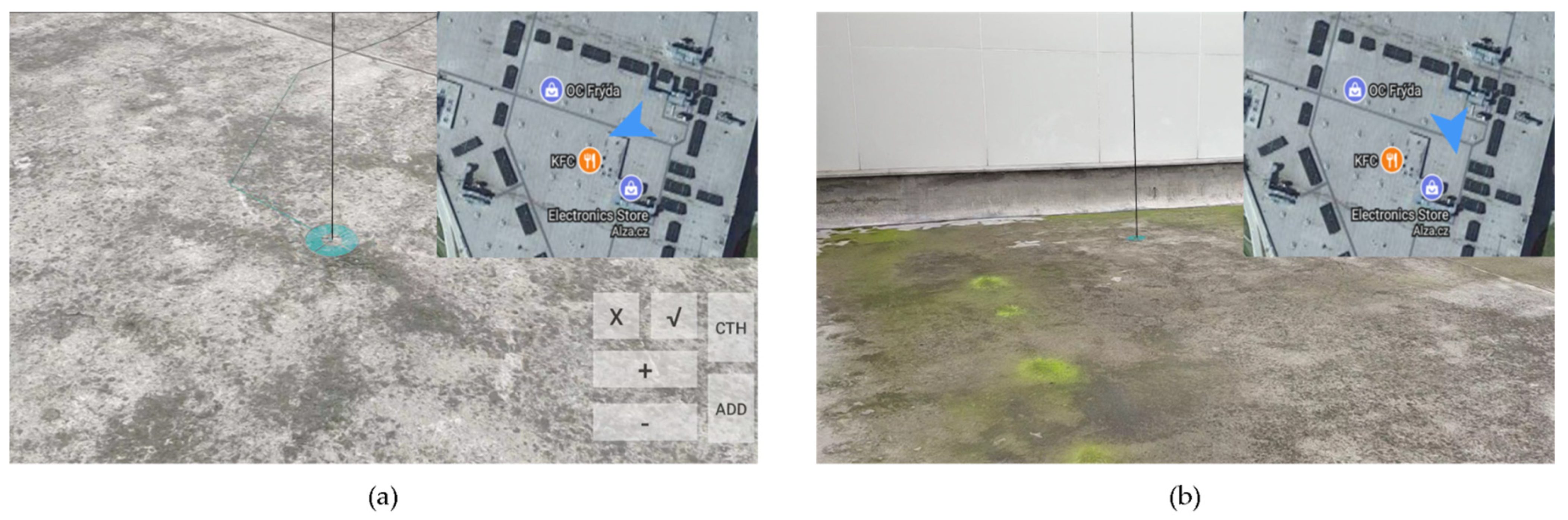
There are two sorts of field of view limits snapping in MAR. The first is that the user cannot see the snapping result of actual or virtual object on the ground at a distance. The other is that the user cannot see the snapping results outside his field of vision. In this study, a combination of marker bars and ground circles is employed to assist produce a distance-related viewer effect in the first issue.
Figure 8 shows two sets of marker bars and ground circles at varying distances. With real-time rendering of marker bars and ground circles, snapping information at various places is constantly user-facing and highlighted. The size change of the ground circle provides an effective perception of the snapping distance. The marker bar model, which is always vertically oriented and whose size is adaptive, provides accurate positioning of the snapping location. Additionally, the real object or virtual object can be captured under various distance conditions.
The system is capable of perceiving virtual constraints beyond the user’s range of view for the second problem. When a suitable actual or virtual item is captured, the system visualizes these constraints outside the user’s field of view, extends with transparent surfaces with a specific tolerance for planes, and expands with dotted solid lines for edges. This approach has the advantage of guiding the user to the proper global constraint extraction rather than being restricted to the current field of view. The requirement here is that the snapping method is not limited to the camera’s field of view, being capable of analyzing the scene globally.
3.4. ARSnap Adaptive Decomposition Method
To offer snapping recommendations in an interactive layout of large-scale spatial data, algorithms should have the ability to analyze large-scale map data effectively, including querying, obtaining, and displaying maps. The regular grid technology is employed to model the map [
49]. In addition, the coordinate system in the AR system is usually a plane nonprojection coordinate system, and the coordinate system of the map is usually a geographic coordinate system. In the calculation to map the coordinates in the map to the coordinates in the AR, because the geographic coordinate system involves spherical coordinates, it is difficult to very accurately calculate the distance, azimuth, area, and other parameters, and a projected coordinate system is usually used. However, the projected coordinate system based on its projection methods can come with corresponding limitations. For example, errors occur in the Mercator projection (equal cylindrical projection on the positive axis) due to the use of equiangular calculations according to the latitude interval, especially in areas with large absolute values of latitudes. The greater the absolute value of the latitude is, the longer the spherical region stretches, and the greater the error. This paper uses the Mercator projection formula to calculate the distance to eliminate the error (see Equation (A4)).
To obtain the map data quickly and in batches in the real-time capture process, the maps are tiled and numbered, which the grid index is based on, at different scale levels. The adaptive decomposition method proposed in this research is based on a regular grid. It divides the converted map data into uniform decomposition subdomains of the equal-area according to the rule of the number of grid rows, columns and elevation value (i, j, h). Assuming that the origin of the map data converted into a plane coordinate system is (x0, y0), the display tile size of the AR map is tile size, and the actual distance represented by 1 pixel on the AR map screen is the resolution. The map framing formula based on a regular grid is shown in Equation (2). The row number and column number of the coordinate point (xN, yN) is calculated after rendering the map:
During the interactive capture process, the corresponding map area of the AR viewport changes. This method extracts a new grid based on the map area change, uses the new grid to extract the original data and the new data, and reflects the extraction results to the new octree grid index. The index data are dynamically updated by this method [
50,
51].
The AR snapping model based on adaptive decomposition is shown in
Figure 9. First, the snap grid is initialized through the virtual visualization range of the AR viewport and the initialization information of real environment recognition. After the snap grid is established, we query the virtual constraint data of an a priori map through the initial viewport range and establish an octree index database. These index data are snapped and calculated by the 3D virtual constraint module described in
Section 3.3. When the user performs screen interactive gesture operation or camera moving interactive operation, for the data generating new browsing area, we start the grid reconstruction task based on adaptive decomposition (hereinafter referred to as adaptive decomposition module). The adaptive decomposition module first converts the coordinates of the new area generated by interaction and calculates the spatial coordinate range with unified geographic reference to the map’s virtual data. Then, we adaptively calculate the map range near the viewport according to the moving direction of the viewport, lock the subdomain range according to the field of view in this direction, merge the new range of the subdomain and the original map range to form a new map range, calculate the row and column number of the map range in the map grid, and update the effective range of the viewport according to the row and column number. The corresponding map virtual data are obtained through the row and column number, and the snap grid database is updated. Then, the index data are extracted from the snap grid database and updated to the octree index database. Finally, the AR snapping model responds to the new interactive snap operation of the application user through the updated octree index database.
3.5. ARSnap Visual Modeling
The visual model and related rendering are required to supplement the information of the real scene in AR [
52]. To keep the information to be relevant or meaningful, the models must be located and displayed in a way that they are integrated into the real world in terms of alignment, perspective, and grounding.
When ARSnap detects any horizontal plane, the corresponding virtual prior model must be properly projected on the image plane of the mobile screen to guide the user’s interaction behavior to obtain the correct capture calculation results. To this end, the actual pose of the model must be estimated, including direction and position calculations. The 2D code or gradient is used to orient the detected features to compare with the 2D code or gradient of the corresponding feature in the target model to achieve the above purpose. In addition, the distance between adjacent features helps to calculate the scale. The above process results in the associated rotation matrix R and translation vector t, which can project each point of the virtual prior model on the moving screen, according to Equation (A8).
In the process of MAR snapping, the user aims the camera at the corresponding target and carries out two natural interaction modes: gesture interactive operation of touch screen and body motion operation of mobile camera to modify and confirm the real-time spatial target capture results. Based on the above ARSnap visual view model, the visual views of various spatial target snapping results are shown in
Figure 10.
4. Experiment and Discussion
The ARSnap prototype system based on Android ARCore is implemented to test the capture function. The entire testing contains snapping on different devices in the real scene and the real crowd, on different complex scenarios and usages. In addition, the experiment also compared the snapping time against different virtual constraints in the real scene, the acquisition results with snapping and without snapping, and the accuracy with different capture algorithm. The capture results of indoor environments with MagicPlan and ARPlan3D are also analyzed, to examine whether ARSnap outperforms the popular applications. More details about MagicPlan and ARPlan3D can be found in references [
53,
54,
55].
We evaluate our approach from several aspects. First, through the time-consuming analysis and robustness analysis of each execution process within ARSnap, we show the quantitative results of multiple sets of practical application scenarios, which proved the effectiveness of the ARSnap algorithm. Second, we compare our capture results with methods based on spatial range queries [
29]. Third, we show the qualitative results of a set of newly collected indoor and outdoor scenes.
4.1. ARSnap Spatial Data Capture Quantitative Experiment
Common capture algorithms include the aforementioned traditional capture algorithm (based on the DB space query algorithm), which constructs query conditions according to spatial relationships such as intersection, containment, and vertical parallel through the constructed spatial objects, traversing points, lines, surfaces, and a matching type dataset. The algorithm performs a spatial query and obtains the result record set with each visible layer as the unit. The result record set includes the point, line, area, text, and other element objects of all visible layers in the current map. In addition, based on the capture algorithm of the fixed grid model, the point group is divided into grids, and a spatial index is established to achieve efficient capture. The capturing algorithm introduced in this article, based on the dynamic grid model and the dynamic distributed grid, can dynamically model the view elements according to the geographic range of the map scale, form a memory index list covering the full view of the map, and query and space objects according to the spatial index. Relation judgments are used to capture objects. For 3D nodes (including the intersection of nodes and lines), surface points, line points, vertical lines, and extension lines, constituting five types of graphics, we compare the operating efficiency of these three spatial objects capture algorithms (time consumption in milliseconds) (
Table 1).
We find that the average capture time based on the dynamic grid model capture algorithm proposed in this paper is within 70 ms for the five graphics types of endpoints, nodes, line points, vertical lines, and extension lines, while the average capture time based on the DB space query algorithm is more than 550 ms, and the average capture time of the capture algorithm based on the fixed grid model is also more than 100 ms. The capture algorithm proposed in this paper takes time to capture significantly better than the other two algorithms.
We also compare the average time consumption of this algorithm in the subprocesses (
Table 2). The average time consumption of the grid index query is within 15 ms, and the average time consumption of the target capture and recognition process is within 30 ms. The result status is drawn; the average time is within 22 ms, and the total average time is within 70 ms. The spatial target capture algorithm based on the dynamic grid model designed in this research has low time consumption and can efficiently achieve graphics capture.
Finally, we compared the most conservative capture conditions with the accuracy of traditional snapping and all snapping events. We conducted multiple sets of target area variance analyses in the subjects; the target areas contained prominent characteristic lines and points, nonobvious characteristic lines and points, etc., which are close to the production environment of the actual AR system data acquisition [
49]. The results show that there is a significant positive effect on ARSnap in comparison with nonsnapping and traditional snapping.
Among them, the comparison between nonsnapping and snapping proposed in this article is the most significant, the error rate of the collection results is generally low, and the accuracy of the collection results is improved from approximately 3 decimeters to 2–5 cm. Similarly, from the comparison of traditional snap and ARSnap in this article, the capture in this article has significantly improved the acquisition accuracy of complex graphics data and long-distance and stereo data. This is due to the use of virtual 3D constraint equation calculation technology to improve complex 3D graphics. The precision of this method reduces the error rate of manual free-style operations. In addition, incorporation of the dynamic update-index data mechanism of the adaptive grid greatly improves the accuracy of capturing large-scale data in the AR map. The specific accuracy comparison results are shown in
Table 3.
4.2. ARSnap Spatial Data Capture Qualitative Experiment
In this section, we test the newly collected indoor and outdoor scenes and systematically verify the qualitative results of the capture algorithm introduced in this paper. The alignment task and the nonalignment task in the capture are compared.
Since the method proposed in this paper is based on 3D computational geometry technology, it supports real-time geometric modeling of all prior data and collected data. According to the direction of the AR camera window, the virtual constraint database after geometric modeling can be queried, and the real-time capture conforms to the 3D virtual constraint of regular 3D surface points, 3D lines points, 3D midpoints, 3D endpoints, 3D parallel lines, 3D extension lines, 3D elevation lines, 3D edge lines and other data types, which do not require much when realizing AR interactive data collection data can be successfully acquired by moving. This capture method reduces the time required for interactive work, thereby reducing fatigue. Furthermore, the complementary use of many virtual constraint types and the threshold range of the capture alignment of each data type can be adjusted according to the tolerance, which improves the real-time response ability of the AR capture system and the environment, especially the feedback on the accuracy of less than 5 cm, which can capture far better than not catching [
26]. Based on AR visual-inertial navigation and the 3D ray algorithm to capture any point on the specified 3D plane, the comparison result is shown in
Figure 11.
We test the effects of the captured visualization results on the human eye. We separately capture the endpoints, breakpoints, points, edges, points on the surface, extension lines, horizontal lines and vertical lines commonly used in GIS data collection and verify them from the perspective of the user experience.
Figure 12 and
Figure 13 summarize the AR capture test results of three data types in GIS data collection.
In order to verify the solution of the capture algorithm in this paper to the spatial location judgment of three-dimensional geographical entities and the relationship judgment of 3DGIS indoor building model, and also to test the accuracy of the capture algorithm in spatial data modeling, we capture a group of doors and windows of buildings, respectively, and verify them from the Perspective of user experience.
Figure 14 summarizes the test results of capturing interior building doors and walls based on 3DGIS semantic constraints.
Finally, to determine whether the ARSnap proposed in this article can provide similar results to the reviewed application, we conduct a qualitative comparison test between ARSnap and the reviewed application. The test task is to capture a room as close as possible to the original image. ARSnap develops a 2D view module that displays the captured results in the application. It also supports exporting the collected results to generate in Unity so that the generated results can be superimposed on the top of the original room layout (CAD file) for comparison with the original room layout [
56]. A side-by-side comparison of the results collected in the same room is shown in
Figure 15.
Comparative experiments show that the selected applications can correctly capture the overall layout of the room. RoomScan and ARSnap as proposed in this article have the best snapping and alignment capabilities. ARSnap with adaptive decomposition method has shorter alignment time than RoomScan. Since all the walls are straight, the collection results of the 3D horizontal lines, 3D vertical lines, and 3D extension lines used in this paper are almost completely consistent with the wall layout of the original room. ARPlan3D and ARSnap yield some length errors when measuring walls. The reason is that both of them use Android’s ARCore engine, and the accuracy of pose estimation in a plane environment is slightly poorer than the ARKit engine used by RoomScan and Magicplan. The comparison shows that RoomScan and ARSnap are closest to the original room layout, and both show very similar results. The collection efficiency of ARPlan3D is very high, and it is the fastest collection of all applications, but the final result is quite different from the layout of the original room. Magicplan’s door and the starting reference are aligned well, but when moving to a far corner, a calculation error occurs.
In order to further verify the availability of the 3D model capture method proposed in this paper, we conduct complete 3D model acquisition for two groups of indoor infrastructure. The acquisition results include geometric information such as length, width, height, window and door, style and model category. This information can be displayed and further applied through modeling software import. The modeling results of Indoor 3D model obtained based on ARSnap in unity are shown in
Figure 16.
4.3. Discussion
The present study was designed to develop a fast and accurate spatial target snapping method. Taking the spatial data of the same building outline as an example, the ARSnap algorithm (our method) is significantly more efficient and precise than the common methods. Due to an optimized adaptive grid dynamic updates and limiting snapping field of view, it is practical for the rapid acquisition of build outlines in small area and is not restricted to camera types such as binocular cameras or depth camera. Therefore, it is applicable for miniature camera and other small equipment. While the traditional algorithm requires a large amount of human motion and a long processing time for the environment perception calculation.
When modelling the indoor 3D models of general meeting rooms or buildings, the accuracy of the snapping algorithm presented in this paper is nearly 20 times better than the accuracy without snapping. The findings reported here suggest that the extraction of virtual constraints from the real environment in the 3D snapping method is significant for AR spatial data acquisition [
29].
In contrast to the existing snapping approaches, our proposed ARSnap is a fast and accurate method for snapping the 3D spatial elements, such as the 3D extended lines, 3D vertical lines, 3D gates and irregular 3D objects. In regularized 3D alignment and result refinement, ARSnap has significant advantages over other methods. However, our research may have several limitations. Using the AR engine of the smartphone [
57], the accuracy of our method for position estimation in complex environments has a lot of room for improvement compared to applications with Lidar and binocular cameras. Furthermore, the operation switching heights and state changes is not intuitive and causes visual confusion. It is possible that hiding unnecessary information and only displaying them when altering height is a good practice.
The adaptive decomposition-based method proposed in this paper can adapt to the rapid capture and visual loading of various map data types, and support the real-time and accurate display of different capture results, so as to achieve the maximum efficiency of vector map visualization in MAR.
Finally, by mapping the spatial information generated by the capture process and capturing results from the two-dimensional screen to the physical world, the three-dimensional model of the building is directly recognized, and the corresponding irregular surfaces such as bottom, wall, top, door and window are superimposed on the actual building with mobile devices, so as to locate and correct the potential capture results on site.


