
Study on Applicability of Energy-Saving Devices to Hydrogen Fuel Cell-Powered Ships


Department of Naval Architecture, Ocean and Marine Engineering, University of Strathclyde, Glasgow G4 0LZ, UK
*
Author to whom correspondence should be addressed.
J. Mar. Sci. Eng. 2022, 10(3), 388; https://doi.org/10.3390/jmse10030388
Submission received: 13 January 2022
/
Revised: 28 February 2022
/
Accepted: 2 March 2022
/
Published: 8 March 2022
(This article belongs to the Special Issue Advancements in Marine Renewable Energy and Renewable Powered Marine Vehicles)
Abstract
:The decarbonisation of waterborne transport is arguably the biggest challenge faced by the maritime industry presently. By 2050, the International Maritime Organization (IMO) aims to reduce greenhouse gas emissions from the shipping industry by 50% compared to 2008, with a vision to phase out fossil fuels by the end of the century as a matter of urgency. To meet such targets, action must be taken immediately to address the barriers to adopt the various clean shipping options currently at different technological maturity levels. Green hydrogen as an alternative fuel presents an attractive solution to meet future targets from international bodies and is seen as a viable contributor within a future clean shipping vision. The cost of hydrogen fuel—in the short-term at least—is higher compared to conventional fuel; therefore, energy-saving devices (ESDs) for ships are more important than ever, as implementation of rules and regulations restrict the use of fossil fuels while promoting zero-emission technology. However, existing and emerging ESDs in standalone/combination for traditional fossil fuel driven vessels have not been researched to assess their compatibility for hydrogen-powered ships, which present new challenges and considerations within their design and operation. Therefore, this review aims to bridge that gap by firstly identifying the new challenges that a hydrogen-powered propulsion system brings forth and then reviewing the quantitative energy saving capability and qualitive additional benefits of individual existing and emerging ESDs in standalone and combination, with recommendations for the most applicable ESD combinations with hydrogen-powered waterborne transport presented to maximise energy saving and minimise the negative impact on the propulsion system components. In summary, the most compatible combination ESDs for hydrogen will depend largely on factors such as vessel types, routes, propulsion, operation, etc. However, the mitigation of load fluctuations commonly encountered during a vessels operation was viewed to be a primary area of interest as it can have a negative impact on hydrogen propulsion system components such as the fuel cell; therefore, the ESD combination that can maximise energy savings as well as minimise the fluctuating loads experienced would be viewed as the most compatible with hydrogen-powered waterborne transport.
1. Introduction
The decarbonisation of waterborne transport is arguably the biggest challenge faced by the maritime industry presently. By 2050, the International Maritime Organization (IMO) aims to reduce greenhouse gas emissions from the shipping industry by 50% compared to 2008, with a vision to phase out fossil fuels by the end of the century [1]. To meet such targets, action must be taken immediately to address the barriers to adopt the various clean shipping options currently at different technological maturity levels. Green hydrogen as an alternative fuel presents an attractive solution to meet future targets from international bodies and is seen as a viable contributor within a future clean shipping vision [2]. The cost of hydrogen fuel—in the short-term at least—is higher compared to conventional fuel; therefore, energy-saving devices (ESDs) for ships are more important than ever as implementation of rules and regulations restrict the use of fossil fuels while promoting zero-emission technology. However, existing and emerging ESDs in standalone/combination for traditional fossil fuel driven vessels have not been researched to assess their applicability for hydrogen-powered ships, which present new challenges and considerations within their design and operation.
Therefore, this review aims to identify the applicability of the currently developed energy-saving devices (ESDs) that can be applied to the exterior of the ship to hydrogen fuel cell-powered ships. This aim is achieved through a number of objectives: firstly, understanding hydrogen power amongst other clean fuel options and the key challenges that need to be addressed for commercial viability of the hydrogen fuel cell-powered ship propulsion systems; secondly, identifying the key components of hydrogen fuel cell propulsion systems and the new challenges that arise in ship operation; finally, quantitatively reviewing the energy saving potential of existing and emerging ESDs and identifying qualitive additional benefits that could improve the performance of hydrogen fuel cell-powered ships.
The review is structured as follows: Section 2 describes the methodology and Section 3 describes the clean shipping future vision and the future technologies available that could decarbonise the shipping industry. Section 4 discusses hydrogen fuel cell-powered ship propulsion, discusses current demonstrator projects underway, identifies key components of the hydrogen fuel cell-powered propulsion system, and identifies the challenges of the new propulsion system and how this relates to ship operation. Section 5 discusses the various types of energy-saving devices that can be installed onto marine vessels, categorised in terms of location on the ship. Finally, Section 6 summarises the review with some concluding remarks.
2. Methodology
A meta-analysis was performed on existing and emerging ESDs through a comprehensive review of existing studies. Keywords and their combinations such as hydrogen, hydrogen powertrain, fuel cells, maritime, ships and automotive were used to identify and understand the challenges of hydrogen fuel cell-powered propulsion systems. The literature on hydrogen fuel cell-powered technology applied to ships is limited as this technology is not applied at scale within the industry yet. Therefore, the literature review was expanded to fuel cell technology used within the automotive industry. Keywords and their combinations such as energy-saving device, propulsion efficiency, drag reduction, marine propellers, and ship performance optimisation were used to identify existing and emerging ESDs within the shipping industry. The literature was then filtered based on their relevance and quality of the paper, with highly regarded peer-reviewed journals preferred and unverified news articles and internal reports used sparingly.
The energy-saving devices were then categorised by the location on the ship that they would be installed on, such as hull resistance reduction measures, propeller flow conditioning devices, propeller and hub modifications, manoeuvring energy-saving devices and, finally, renewable energy assisted propulsion. The main descriptor of interest within the literature review was the quantitative energy saving of the ESD when compared to a reference design. Secondly, qualitative advantages were recorded, such as reduction in cavitation and underwater radiated noise, as they can benefit the ship in other means, such as reducing cavitation-associated maintenance, cost and reduced impact on marine wildlife, while potentially mitigating negative impacts on the hydrogen fuel-cell powered propulsion system. The methodology in which the energy saving was recorded as disparity in results between model-scale test campaigns, full-scale demonstrations and CFD is common. If more than one case study was conducted, for example, the results from the full-scale demonstrations and real ship data were given priority over model-scale CFD results, although both sets of results were discussed. The vessel type in which the ESD was applied to was also recorded to be able to provide a recommendation of ESD combinations for specific types of vessels. The technological readiness level (TRL) was assigned based on the maturity of the technology, 9 being commercialisation of the technology with a number of vessels operating with the ESD installed and 1 being initial concept design. Generally, the lowest TRL considered within this study was 2/3, where model-scale CFD had been conducted to formulate the ESD’s energy saving capability. The TRL was used to identify the technologies that are the most mature, and was thus available to be exploited instantly with hydrogen fuel cell-powered propulsion systems, and it was used to identify the emerging ESDs that need more research but remain promising based on initial results. The above data in addition to existing studies on ESD combinations were then used to formulate a recommendation for a combination of ESDs capable to maximise the energy saving potential on specific vessel types, as well as minimise the negative impact on the hydrogen fuel cell-powered propulsion system.
3. Clean Shipping Future; Vision and Technology Options
3.1. The Clean Shipping Vision
The State of the Climate 2020 report from the American Meteorological Society stated that the dominant greenhouse gases (GHG) have continued to increase in 2020 [3]. In 2019, the concentration of CO2 was 47% higher than preindustrial level [4]. GHG’s and CO2 contribute to climate change which has a well-documented adverse effect on human health as well as wildlife, causing increased risk of flooding, extreme temperatures and rise in sea levels which can lead to loss of livelihoods, crop yields and a shift in wildlife ecosystems [5]. Therefore, reducing greenhouse gases, carbon emissions and other toxic pollutants such as nitrous (NOX) and sulphur (SOX) oxides across all sectors—air, land and sea—is an important consideration in the development of more sustainable transport for the future.
It is estimated that shipping activities contribute to 3 to 5% of global CO2 emissions and over 5% of global SOX emissions [6]. While automotive drive systems have become more advanced, with the aim to reduce fossil fuel consumption and carbon emissions with electric vehicles becoming commercially available to the general public, the development of sustainable propulsion technology for ships has lagged behind, predominantly due to the lack of strict regulations on the environmental impact of waterborne transport being imposed [7,8]. The lack of such strict rules and regulations has maintained cost of ownership as the principal technological driver which has prolonged the use of economical but environmentally toxic traditional diesel engines coupled with cost-effective heavy fuels [9].
However, this has started to change. In 2018, the International Maritime Organization (IMO) adopted an initial strategy for the reduction in GHGs from ships, setting out a vision to phase them out as a mattery of urgent by the end of the century, with at least a 50% reduction by 2050 compared to 2008 levels [1]. Therefore, it is clear that the IMO envisage the future of shipping to be driven by fuels that do not produce the levels of GHGs seen by the traditional diesel engines. This is a crucial step to sustainable waterborne transport following the previous regulations, namely, the Energy Efficiency Design Index (EEDI), Energy Efficiency Existing Ship Index (EEXI), Existing Vessel Design Index (EVDI), Carbon Intensity Indicator (CII) and the enhanced Ship Energy Efficiency Management Plan (SEEMP), which were drawn up to promote and manage the use and quantification of energy-efficient equipment and engines on new and existing ships to reduce the levels of CO2 emitted into the atmosphere from the shipping industry.
Design indices such as the EEDI, EEXI and EVDI are to measure how efficiently a ship has been designed, built or retrofitted and refers to the theoretical carbon intensity of the vessel. These values will not change over the operation of the ship. EEDI, EEXI, EVDI can be defined in [10]. The CII rating scheme addresses the emissions in actual operation, which comes into effect in 2023 for all cargo, RoPax and cruise vessels above 5000 GT and trading internationally. The Annual Efficiency Ratio (AER) is a primary concern of the CII, which refers to the actual carbon intensity and represents how well a ship is operated. The AER will be used as the carbon intensity metric by the Poseidon Principles—a new global framework for responsible ship finance. They establish a global framework for assessing and disclosing the climate alignment of ship finance portfolios and are consistent with the policies and ambitions of the International Maritime Organization [11].
Meanwhile, the UK Government issued a Clean Maritime plan in 2019 with the ambition to achieve zero-emission shipping by 2050, expecting that, by 2025, all vessels being ordered to operate in UK waters will have zero-emission capability, with some zero-emission commercial vessels in operation [12]. Mission Innovation, launched alongside the Paris Agreement in 2015, issued a joint zero-emission shipping mission statement in 2021 co-lead by Denmark, USA and Norway with the aim to introduce zero-emission-capable commercially viable vessels into the ocean-going global fleet by 2030, scale up production of zero-emission fuels and establish global port infrastructure to support vessels operating on zero-emission fuels [13]. Therefore, this would encourage ship owners, when renewing their fleets, to opt for the zero-emission vessel option naturally. Other countries such as the UK, Morocco, India, Singapore, France, Ghana and South Korea are amongst the partners that have endorsed the mission statement to drive innovation in the global maritime value chain towards a zero-emission tipping point by 2030 and allow for rapid decarbonisation of the sector thereafter. Therefore, zero-emission shipping is on the agenda for many countries to collectively address one of the primary challenges within the maritime sector. The 21st-century “maritime silk road” is a cooperative initiative within China, in which Chinese firms are involved in either building or operating 42 ports in 34 countries. The support of China, which is the world’s largest exporter of products and the world’s largest shipbuilder for energy saving and carbon emission reduction, is crucial to the adoption of the IMO aim to at least halve the global shipping sector’s greenhouse gas emissions by 2050. China’s proposal to achieve net zero emissions by 2060 could be the turning point for fossil fuel markets and the global energy transition, but the scale of the task is ambitious and the roadmap still vague. Although the government supports this timeline of the IMO landmark, much discussion of this is not found from China’s shipbuilders. While China’s shipping companies and ports are making progress on cleaning up air pollution, especially sulphur, there is a lack of debate on green hydrogen, or other potential zero-carbon fuels. More communication between China’s world-leading renewable energy firms and its world-leading shipping sector will stimulate the development of China’s zero-emission, to place the country at the head of a future carbon-neutral global trading system.
Regardless, as alternative fuels become used more regularly through strict regulations, energy-saving devices (ESDs) will become more important than ever as the cost of alternative fuel will likely be higher than conventional fuels currently; therefore, all ship owners will have a heightened incentive in reducing ship fuel consumption and their fuel bills. Although, ESDs have been continually developed to meet IMO’s guidelines over the last few decades. On their own they will not meet IMO’s targets and align with the vision of the future for waterborne transport; therefore, investing in zero-emission technologies to make them more economical and commercially viable should be a primary focus if the ambition and future vision for shipping of international bodies and government are to be met, and met within the expected time frame.
3.2. Zero Emission Shipping Technology Options
The route to decarbonisation for the shipping industry will depend on the commercial viability and technology readiness level of the zero-emission technology options available. Zero-emission technology can be categorised as either zero-carbon or net-zero-carbon. Zero-carbon technologies are technologies which expulse zero greenhouse gas emissions such as ammonia, hydrogen and batteries, given that the production of the electricity to supply the propulsion system is from a ‘green’ renewable energy source such as solar, wind, wave or tidal. In contrast, net-zero-carbon technologies are fuels such as methanol that contain carbon but do not increase the total anthropogenic carbon balance in the atmosphere and use the CO2 from the air for production [14].
Batteries are a zero-emission technology option, although large cargo vessels travelling long distances will not be able to complete the journey on batteries alone; however, for small light craft travelling short distances or as part of a hybrid system for longer journeys, it is certainly a feasible solution for decarbonisation if the electricity is produced from renewable energy sources [15]. Nuclear powered ship propulsion expulses zero CO2, SOx, NOx or particle matter, thus meeting the criteria for decarbonisation, and is used for military applications such as powering submarines. However, the lack of adoption for commercial shipping is largely due to the high upfront capital costs for the appropriate infrastructure necessary while there are also concerns of safety, decommissioning, high insurance and public perception, which makes nuclear an unlikely zero-emission technology option for the future of waterborne transport [16].
The use of methanol as a shipping fuel has been around for several years since the conversion of RoPax ferry Stena Germanica [17]. It is not as harmful to the environment when compared to the heavy fuel oils (HFOs) used in conventional diesel engines [18], but it is not totally carbon-free, using the carbon dioxide present in the air for production. However, it is an attractive alternative fuel as it does not contain sulphur and the emission of NOx and particle matter during combustion is low. While infrastructure for fuels such as hydrogen are not in place and technology for safe storage and deployment is not at a mature level, methanol can use the same infrastructure for distillate fuels and the technology for safe storage and deployment is at a mature level where the class community understands it is safe and practical. However, a key concern for methanol is the availability of the fuel at scale for a global fleet of ship, to meet such demands one would require significant investment. Another key concern is that methanol is also toxic to humans; however, the fuel has been safely handled for more than 50 years, with conventional fuels such as diesel or heavy fuel oil no less poisonous. It is also miscible in water and can biodegrade rapidly in the event of a spill, making it less hazardous to the environment when compared to traditional fuels [15]. In addition, due to methanol being toxic to humans and having a higher explosive range when compared to HFOs or ammonia, it has been suggested that more monitoring systems would be required for safe usage when compared to current fuels [2]. Therefore, methanol is an attractive option in the short-term, with its low emission capability, readily available infrastructure and mature technology for safe storage and deployment making it an excellent candidate to support the transition to net-zero carbon emission shipping. However, due to the non-carbon free nature of the fuel, it is hard to envisage methanol as being the sole provider of a clean shipping future.
Green ammonia is another zero-emission technology candidate that has gained traction in the maritime industry as an alternative marine fuel, particularly because there is no carbon content, and therefore no carbon emissions released in the process. However, ammonia is not totally emission free, as the process can lead to NOx emissions, and it is highly toxic, with only small levels of exposure required for loss of consciousness, making port authorities and regulators reluctant to approve bunkering ammonia fuel at ports [19]. In addition, it is also corrosive, so storage casing material must be carefully considered, but it is not flammable, so there is a low risk of fire. Ammonia is also relatively easy to store when compared to the likes of hydrogen, as it can be stored at ambient temperature by applying 10 bar or at ambient pressure at −34 °C. Today, most ammonia is produced from natural gas, commonly known as ‘grey’ ammonia, which is not zero-carbon when the whole lifecycle is considered; therefore, ship owners must consider the whole supply chain through from fuel production, transport, storage and the final use onboard to avoid shifting the carbon emission problem upstream instead of solving it entirely. Ideally, in the future, ammonia will be produced from ‘green’ hydrogen supplied by renewable energy sources, ensuring zero-carbon emissions within the supply chain of the fuel, and this is the ambition of the shipping industry [20]. If feasible, green ammonia has many desirable attributes that would aid in the decarbonisation of the shipping industry although there are still challenges to overcome to view this as a concrete possibility in the current state.
Green hydrogen, produced from renewable energy sources such as tidal and wind, presents an attractive solution to achieve the future decarbonisation ambitions of the shipping industry. It is one of the most readily available elements on earth, although to unlock its potential as a fuel, processes like electrolysis are necessary to split hydrogen from water. It is completely carbon-free if produced from renewable energy sources, with the only by-product being water [21]. However, hydrogen as a fuel presents its own challenges. At ambient pressure, hydrogen has a low energy density, meaning that it must be stored as a highly compressed gas, as a liquid or through metal hydrides to increase energy density and reduce the fuel storage space required onboard. Additionally, there must be careful consideration of the storage material used because hydrogen can permeate through walls. However, storage as a compressed gas will bring about its own challenges as additional infrastructure and structural considerations will be needed to maintain the pressure, while for storing as a liquid, the hydrogen will be between roughly −260 °C and −240 °C, which requires a significant amount of energy to maintain at that temperature and could increase total energy demand by up to 30% [2]. In addition, storing as a liquid will create a problem known as ‘boil off’, where the liquid begins to evaporate, which will require further energy to reliquefy. Metal hydrides would result in increased weight due to the metal used for absorbing the hydrogen using chemical bonding. There is a lack of infrastructure for the bunkering of hydrogen fuel, while it can be highly flammable with the potential to be explosive. Additionally, it is colourless and odourless making detection of leaks difficult. Therefore, such safety concerns would require further monitoring systems, training, rules and regulations to ensure safe use of hydrogen fuel for ships and port authorities. Although there are still several challenges to address primarily relating to the safety, storage, transport, upscaling of green hydrogen production and bunkering infrastructure, it is also a strong candidate to contribute to the zero-emission targets of the shipping industry [22].
Zero-emission technology such as batteries, methanol, ammonia and hydrogen can contribute to the transition to net-zero, depending on if the specific challenges for adoption for each fuel are addressed, which will require significant research, development and investment. The cost of clean fuel when compared to traditional ‘black’ fuels is also a barrier to adoption, which could be addressed through a carbon levy which has been proposed by the International Chamber of Shipping (ICS). The choice of technology for transition will vary depending on the type of vessel, journey time/route as well as cargo choice so a one solution fits all is unlikely. However, green hydrogen is the cleanest potential fuel and the simplest to produce, and is has been suggested to be the strongest candidate to achieve the clean shipping future after transition on a global scale [2], thus future discussions within the paper will be focussed solely on green hydrogen-powered ships.
4. Hydrogen Fuel Cell-Powered Ship Propulsion
4.1. Examples of Current Hydrogen Powered Ship Demonstrator Projects
Hydrogen-powered ship propulsion has gained a lot of interest as part of the clean shipping future, with projects completed and ongoing to implement hydrogen-power on a variety of different types of waterborne transport, as well as establishing a viable hydrogen supply chain and bunkering infrastructure to meet ambitious targets set by the IMO. Some of the projects that have been completed or underway relating to hydrogen powered ships are discussed.
In 2017, Hydroville became the first certified passenger shuttle that used hydrogen-power through a hybrid hydrogen–diesel engine; fuel cells were not used because they were too expensive, and it was believed that the technology could not be applied to bigger ships at the time. The sensitivity of the fuel cells to salty sea air and the resulting performance degradation was also a consideration in the design, and has been described as the major contaminant for maritime applications [23]. It is used to transport employees from Kruibeke to Antwerp and as a demonstrator for hydrogen-powered waterborne transport [24]. HySeas (I-III) commenced in 2013 as a three-part project with the aim to integrate hydrogen fuelled propulsion onto a ferry operating between Kirkwall and Shapinsay, in the Orkney Islands, located in the North of Scotland. The project looked into the theory of hydrogen power in 2013 (Part-I), while between 2014–2015, a technical and commercial study was conducted to design a hydrogen fuel cell powered ferry (Part-II). At present, HySeas III aims to demonstrate the fuel cells integrated into a marine hybrid electric drive system by demonstrating the developed technology inland, in addition to hydrogen storage and bunkering infrastructure. If successful, the developed technology and knowhow will be used to implement the design onto the ferry [25]. Orkney is a particularly suitable location to trial hydrogen technology, with mature renewable energy technology producing a surplus of electricity, which would be available to produce green hydrogen such as wind turbines and more recently, tidal energy where the world’s most powerful tidal turbine Orbital Marine Power’s O2 was deployed in Orkney waters [26].
European innovation project FLAGSHIPS aims to deploy two operated compressed hydrogen fuel cell vessels, the first being an inland vessel expected to be deployed in river Seine, Paris by September 2021 [27]. While the MARANDA project, which runs from 2017 to 2021, aims to use a 165 kW hydrogen proton-exchange membrane (PEM) fuel cell for auxiliary power on a Finnish research vessel [28].
HyShip aims to utilise liquid green hydrogen on a new build ro-ro vessel to be operational by 2024 as well as establishing a viable liquid hydrogen supply chain and bunkering facility [29]. A group of Norwegian companies aim to retrofit liquid hydrogen-powered propulsion system on a cruise ship by 2023 through a hybrid system with a 3.2 MW hydrogen fuel cell and battery storage, making it the largest fuel cell installed on a ship to date [30]. Danish firm, DFDS aim to manufacture in collaboration with external partners and operate a hydrogen-powered ferry by 2027, Europa Seaways. The consortium has applied for funding from the EU to develop the large ferry. The fuel cell will have a capacity of 23 MW, with current fuel cells rated at 1–5 MW; this will present a significant challenge to address within the demonstration. Conveniently, the ferry will operate from the Copenhagen area, where there is a large resource of renewable energy production from wind farms that will support the supply of green hydrogen through electrolysis [31]. Meanwhile, the first liquid hydrogen carrier—named the Suiso Frontier—is scheduled to leave Japan for Australia as early as this month to pick up its first cargo of hydrogen late this month as part of a pilot project led by Japanese company Kawasaki Heavy and backed by Japanese and Australian governments to show liquefied hydrogen can be produced and exported safely to Japan [32]. Table 1 summarises the key hydrogen-powered propulsion projects.
The success of the above-mentioned demonstrators underway within the next decade will provide a useful benchmark to determine the viability of meeting the ambitious targets set by the IMO for 2050 for decarbonisation of the shipping industry, while also aiding in the reduction in fuel costs with the establishment of a green hydrogen supply chain and bunkering facilities as well as the formation of codes and regulations surrounding the safe usage of hydrogen fuel in the marine industry from well to tank. The interest in hydrogen-powered propulsion will only increase; therefore, it is crucial to understand the key components of the propulsion system and how this will differ from a conventional marine propulsion system to accommodate on existing vessels as a retrofit solution or on new builds in their early design stages.
4.2. Key Components of a Hydrogen Fuel Cell-Powered Propulsion System
It is envisaged that future shipping will run solely on sustainable means with no reliance on fossil fuels; therefore, the hydrogen-powered propulsion system discussed will be as such, although within the transition phase there will likely be some percentage of craft using hydrogen–diesel hybrid solutions until a global commercially viable green hydrogen supply chain and bunkering infrastructure can be established.
A potential future hydrogen-powered propulsion system are shown in Figure 1. The hydrogen could be stored as either compressed gas, liquid or metal hydrides—all with their own challenges. Compared to typical diesel fuel, the volumetric energy density for all forms of hydrogen is considerably less (see Table 2), meaning that, generally, to complete the same route with the same amount of fuel when compared to conventional fuel, the storage required will increase by several times, which will reduce cargo space.
Within the fuel cell, the hydrogen reacts with oxygen supplied by the air intake to produce electricity, which can be supplied to the electric motor to power the vessel. Compared to internal combustion engines, fuel cell technology can achieve a higher efficiency of 65% when compared to roughly 40% [33], although low-speed two-stroke diesel engines commonly used on larger ships can achieve efficiencies of up to 50% with a waste heat recovery system [34]. More recently, the use of fuel cell technology for maritime applications has been reviewed, suggesting that for journeys below 12 h, a liquified hydrogen low-temperature polymer electrolyte (also known as proton exchange) membrane fuel cell (LT-PEMFC) provides a power-dense solution for ships; however, for journeys above 100 h, the limited hydrogen storage density is expected to result in 1.5–5 times larger total system volumes compared to alternative systems [9]. Mekhilef et al. [33] suggested that PEM fuel cell technology was particularly suited for transportation applications such as automotive and buses. DNV GL., Shu et al. [35] conducted a dedicated risk assessment of fuel cells for shipping applications and concluded that the most attractive fuel cell system was the PEM fuel cell followed by the high-temperature PEMFC. The PEM fuel cell is a mature technology being successfully used in maritime applications when compared to its high-temperature counterpart which is still at a demonstrator phase. The major disadvantage of the PEMFC is sensitive to impurities in the hydrogen, a complex water management system (both gas and liquid) and a moderate lifetime. However, they are lightweight and more compact when compared to other fuel cell technologies, which makes them well suited to shipping applications, and they operate at relatively low temperatures, which makes it easier to contain and reduce thermal losses. Xing et al., 2021 [23] conducted a review of fuel-cell power systems for maritime applications and concluded that although fuel cells have significant advantages such as reduced emissions, improved efficiency and low noise operations, drawbacks such as power capacity, durability and economic costs are the main barriers to adoption for the technology. It was also suggested that development in strict rules and regulations, investment in infrastructure in fuel bunkering systems and development of design rules and operational guidelines were necessary as the technology develops.
On the other hand, quick spikes in power demand from the vessel can cause a high voltage drop in the fuel cell in a short time, known as starvation, which can reduce performance and lifetime of the fuel cell [33]. The consensus is that fuel cells can be combined with batteries which can supply the quick spikes in power demand, therefore reducing the negative impact on the fuel cell and improving the responsiveness of the hybrid (battery/fuel cell)-powered propulsion system in such conditions, while overcoming the drawbacks of a battery-only system such as very low distance range and extensive recharging time [36,37]. When the vessel is operated at a low power, such as while loading/unloading, the fuel cell can recharge the battery, while the fuel cell is expected to supply the power demand at cruise speed and maximum power demand supplied by both fuel cell and battery. The fuel cell could also be used to supply auxiliary power for the hotel load of a ship [38]. However, the hybridisation of fuel cells and batteries requires further research to understand their capability to deliver the load demands; thus, an appropriate power management system is critical to create an effective power delivery system [9,39].
4.3. Impact of Transient Power Fluctuations on Hydrogen Fuel Cell-Powered Propulsion
As mentioned in Section 4.2, transient loads can have a negative impact on the fuel cell performance and lifetime, and such time-varying loads can occur when marine vessels are in operation. Transient loads can occur due to: blade passing fluctuations behind non-uniform wake, propeller operating under cavitation and/or ventilation, ship manoeuvring/dynamic positioning, and ship in waves/strong wind [40]. However, in terms of severity, operating in head waves is the most challenging in terms of dynamic loads [41].
However, the limit of time-varying load fluctuations for fuel cell applications for the vast range of waterborne transport in operation still needs to be further investigated and uncovered; this will likely depend on aspects of the propulsion system such as fuel cell stack/battery combination, power management system and power demand of the vessel. Boekhout [39] investigated the implementation of fuel cell battery systems on hydrogen-powered ship propulsion for high-speed craft, suggesting that load changes of above 10% of its maximum power per second should be avoided for PEMFC. It was also deduced that the fuel cell could follow load variations with a low-frequency; however, the fuel cells reach their dynamic limit with high-frequency load fluctuations. For one fuel cell stack, the encounter frequency limit was 1 rad/s, while for a combination of two fuel cell stacks it was 1.2 rad/s. It was recommended, from a power management point of view, for the battery to supply the desired power in high-frequency load fluctuations due to its high responsiveness, protecting the fuel cell. As this may be case-specific, it is reasonable to assume in the current state of developments that any form of reduction in transient load mitigation from the different aspects of ship operation mentioned would be an additional benefit to the vessel, improving performance and prolonging the life of the hydrogen-hybrid propulsion system.
Although energy-saving devices (ESDs) have been continually developed to meet the IMO guidelines over the last few decades, they have not been designed with a scope to be applied within hydrogen-fuelled propulsion systems, which the IMO now sees as a potential future shipping fuel to meet their current ambitious targets. As regulations to achieve decarbonisation tighten, the use of more costly (in the projected short-term at least), alternative fuels will increase, and this will make ESDs more important than ever. Therefore, it is now crucial to identify the challenges of adopting hydrogen-fuelled propulsion for maritime vessels in comparison to the traditional propulsion system, review the emerging and existing ESDs and, finally, how they can be combined in harmony with the hydrogen propulsion system to contribute to solving the technical and economic barriers for the adoption of hydrogen fuel, maximise energy efficiency and meet the IMO’s targets for the shipping industry.
5. Energy-Saving Devices (ESDs) and Their Suitability for Hydrogen Fuel Cell-Powered Propulsion
Energy savings can be achieved through numerous methods, for example, technical measures such as hull optimisation, waste and heat recovery systems installed on the main propulsion plant, and operational measures such as route optimisation, slow steaming and maintenance optimisation [42]. However, this review of focused on energy-saving devices that can be retrofitted or incorporated into new builds on the exterior of the ship.
Energy-saving devices can be categorised into five areas: hull resistance reduction measures, propeller flow conditioning devices, propeller/hub modifications, manoeuvring energy-saving devices and renewable energy-assisted propulsion (see in Figure 2). They vary in general location with respect to the vessel as are shown in Figure 3. Quantitative energy saving or propulsive efficiency savings are reviewed, the method in which the saving was achieved such as model-scale tests, CFD and full-scale demonstrations as well as the vessel types best suited for each ESD. Focus is also given to additional qualitive benefits that could improve the suitability of the ESD for hydrogen-powered propulsion by mitigating aspects of ship operation that can negative impact on the hydrogen propulsion system. Finally, research conducted on combination ESDs are reviewed while combination ESDs that would be most compatible with hydrogen-powered ships based on the available literature are suggested by the author’s as well as a conservative estimated energy saving.
5.1. Hull Resistance Reduction Measures
In shipping, a large part of the fuel is used to overcome hydrodynamic forces, up to 85% [43]; hence, reducing hull resistance is the most direct way to save energy. In this section, three hull-resistance reduction measures are introduced below, including air lubrication, hull coating, and hull vanes. These types of devices generally do not require modification to the vessel’s main propulsion system, thus being potentially compatible with hydrogen-powered ships.
The frictional resistance is significant proportion of the total ship resistance, and the air lubrication system (ALS) reduces it by transferring air between the underwater surface of the hull and the water. According to the gas supply method, as shown in Figure 4, ALS can be divided into three primary types: bubble drag reduction (BDR), gas layer drag reduction (GLDR), and gas cavity drag reduction (GCDR).
In BDR, bubbles mainly exist in the boundary layer and reduce drag by reducing the density of the air–water mixture, but because of the near-wall shear, the bubbles are migrated from the plate surface, which cause the disappearance of drag reduction phenomenon after the air injector few metres. As a result, the air injectors have to be deployed in many places in order to maximise the bubble coverage area, which will subsequently increase upfront costs [43,44]. Moreover, the drag reduction mechanism of BDR is complex, depending on the various bubbles’ sizes and inflow speeds [45,46,47,48,49,50]. For GLDR, it is different from BDR in that, by increasing the injected gas, the bubble flow become the gas layer, which is generally thinner than the boundary layer. Hoang et al. [51] reported a sea trial using ALS on cement carrier Pacific Seagull. In the ballast and full load conditions, the total resistance reduction achieved 11% and 6%, respectively. Another sea trial of a carrier was 162 m in length and 38 m in width by Mizokami et al. [52]. In this experiment, the energy-saving effect increased from 8% to 12% with the air thickness from 3 mm to 7 mm. it should be noticed that, in practice, the effect of drag reduction is sensitive to sea conditions and ship motions [53]. Regarding GCDR, there is a recess on the hull bottom for forming a gas cavity between the hull and water. The gas in the cavity separates the hull surface from the water, and frictional drag reduction in this area is more than 95% [53]. Butterworth et al. [54] reported an investigation of a container ship model using GCDR, and the experimental results showed the total drag reduction varies from 4% to 16%, but at high speed, the air chamber did not seem to work as effectively.
Although air lubrication has been developed for many years and practiced on the planning boat, the application on the large displacement vessel is not yet widespread. However, sea trials of some large displacement vessels have been successful, such as bulk carrier, container carrier, heavy cargo carrier (HCC), chemical tanker, and LNG carrier, and the net energy savings were between 4% to 10% [55]. In summary, ALS does not show any conflict with the hydrogen-powered system. However, it should be noticed that local stress concentration should be considered because of the apertures of the hull for ALS, and the rearrangement of equipment, piping, and ventilation also needs to be considered. Moreover, according to the additional ALS weight, the design parameter maybe needs to be re-evaluated, such as stability and lightship weight [55,56,57]. In addition, the trade-off between the additional space required for the ALS within the hull to provide the energy saving and the space lost that could be used for hydrogen fuel storage must be further assessed.
Hull coating (HC) is also an effective way to reduce the hull resistance via reducing the frictional resistance. As the operation time of a ship increases, the roughness of the hull surface immersed in seawater will increase due to marine biological fouling, shown in Figure 5. As a result, the marine biological fouling causes increased weight and decreased speed, and then it causes an increase in fuel consumption, up to 40% [58]. Abbott et al. [59] reported that, for a 15,000 t deadweight dry-cargo vessel in a coating-failure condition, the journey costs increased by about 77% comparing to a coated condition. The hull coating is necessary for ships in antifouling and the choice of hull coating based on the vessel’s working purpose, cost and maintenance cycle. The development of the antifouling coatings is generally divided into two directions, which are biocide and foul release.
In the past, tributyltin self-polishing copolymer paints (TBT-SPC paints) was the most effective biocide method against biological fouling; it was used on 70% (about 27,000 ships) of the fleet in the word, in 1996, and brought huge economic benefits [58]. However, because of its adverse effects on the environment and the marine ecosystem, it has been banned since January 2003 due to the IMO legislation. Thereafter, the controlled depletion coating (CDP) as the first generation of the tin-free antifouling coating, was commercialised. However, it still has a toxic effect on the environment due to the high copper and biocides. Elsewhere, a tin-free coating that has the same mechanisms as TBT-SPC paints was developed, called tin-free self-polishing copolymers (tin-free SPCs). Because of the self-polishing characteristic, the leached layer is thin and its mechanism lasts up to 5 years [60]. Regarding foul release coating, it is a biocide-free low energy non-polar coatings which provides very low friction and a smooth hydrophobic surface; thus, it is difficult for organisms to attach to the coating. Currently, there are two main categories: fluoropolymers and silicone. Arukalam et al. [61] prepared perfluoro-decyl trichlorosilane-based poly (dimethylsiloxane)—ZnO (FDTS-based PDMS-ZnO) nanocomposite coating, which has anti-corrosion and anti-fouling capabilities, and ZnO improve adhesion via increasing the anti-bacterial ability and smoothness of coating. Xu et al. [62] prepared a polymer using poly (ethylene glycol) (PEO) and poly (2,2,2-trifluoromethyl methacrylate) (PFMA), and then it was mixed with fluorine to form a self-cleaning surface. Comparing to fluoropolymers, silicone has a low price and easier preparation to be commercialized. Selim et al. [63] prepared an ultra-hydrophobic polydimethylsiloxane/Ag@SiO2 core–shell nanocomposite and reported it is cost-effective and has higher self-cleaning properties and long-lasting properties.
Because of the effect of the complex internal and external factors, the antifouling effect and life of a coating system may be different on various ships and its performance is hard to evaluate. However, the coating system as a conventional means of anti-fouling and drag reduction in the process of shipbuilding, its benefits are well-established, and it is generally carried out at the same time as ship outfitting. Regarding a hydrogen-powered ship, there is no doubt that hull coating is necessary and does not conflict with the use of other ESDs, but the choice of the kind of hull coating should depend on hull materials, production costs, and its applications. Although a coating containing heavy metals and booster biocides can provide cost benefits, the implementation of non-toxic antifouling coatings is a trend nowadays in order to meet environmental regulations [64,65].
Hull Vane is an underwater fixed wing fitted after the vessel stern, and it can be retrofitted to existing ships or integrated into new designs (see Figure 6). Hull Vane reduces fuel consumption via following four ways: the lift can provide a forward force as a thrust force; the vertical force provided by lift can correct the trim; the transom wave can be reduced by the negative pressure on the upper surface; and the water resistance on the foil surface can dampen the pitching motion of the vessel and reduce the additional wave resistance [66]. Bouckaert et al. [67] reported CFD analysis of a Holland Class 108 m Oceangoing Patrol Vessel (OPV) applying a Hull Vane. The results showed that the total drag reduction achieved 15.3% and the Hull Vane provided a positive effect on the seakeeping of ships. For 2 m waves, a 2.4% heaving RMS (root mean square) of reduction and an 8.1% pitching RMS of reduction can be provided. Regarding the case of 4 m waves, the reduced heaving RMS was 3.1% and reduced pitching RMS was 6.8%. Furthermore, a 12.5% reduction in fuel consumption can be provided by applying Hull Vanes on Holland Class 108 m OPV [68]. In another CFD study of the Hull Vane application on 50 m Patrol Vessel of AMECRC#13, by Uithof et al. [66], an obvious drag reduction was obtained, up to 32.4%. Meanwhile, it is affected by where it is positioned, and the horizontal position has more drag reduction difference, which is up to 13%, but between Froude number (Fn) 0.6–0.8, the differences are small due to the more uniform wake. Furthermore, it should be noted that the Hull Vane could provide a 20.9% reduction in amplitude in regular waves, which had 50 m length and 1 m height, and this phenomenon had a significant benefit for a hydrogen-powered ship in reducing pitching motion and improving stability. In another study of 167 m RoPax vessel, by Uithof et al. [69], the tank tests using an 8 m model showed the drag reduction achieved 10.1% at 17 kn and 15.5% at 21 kn. Hagemeister et al. [70] analysed the drag and propulsion effect of the appended Hull Vane and the integrated Hull Vane on a 61 m patrol boat by CFD method. The fuel consumption reduction in the appended Hull Vane was about 15% and for the integrated Hull Vane, it was about 9%. Furthermore, the performance of a retrofitted Hull Vane applied on a model DTMB 5415 hull was investigated in the towing tank and the full-scall performance also was predicted by two methods [71]. This research showed, in the model-scall test, Hull Vane provided 3.8% and 5.5% of the drag reduction in still water and waves, respectively, and predicts that the drag reduction was about 10% in the full-scall application. In sea trials, the Hull Vane showed a significant effect in drag reduction. A sea trials study using a 55 m supply vessel Karina retrofitted with Hull Vane showed a 15% drag-reduction effect compared with a vessel without Hull Vane. Another vessel, which was a Dutch yacht integrated Hull Vane, obtained a drag reduction in up to 23% [72].
From existing studies, the Hull Vane’s drag reduction effect has been proven. Regarding the existing ships, an additional Hull Vane could be considered because of the short retrofitting time. For the new ships, depending on the lower resistance, other systems could have more choices to reduce the building cost at the design stage [67]. In general, the total length of a ship always has limitation, thus the additional length due to the Hull Vane should be considered. Moreover, the manoeuvrability would be reduced because of the directional stability [69]. In summary, for the hydrogen-powered ship, a Hull Vane can be considered as an ESDs to integrate during the design phase.
A regenerated development, the bow foil (see Figure 7) is like the Hull Vane in that it can reduce various undesirable ship motions and it has gained interest amongst ship owners to reduce ship fuel consumption. The bow foil is a well-known concept, with multiple research studies conducted to investigate the effect of bow foils on ship propulsion and motion [73,74,75,76,77]. In 2019, retractable bow foils, made by company Wavefoil, were retrofitted to the ferry, M/F Teistin which achieved a 9% reduction in ship fuel consumption [78]. The retractable bow foils reduce the movement of the ferry in waves such as the large pitch motions induced by head and bow waves, while also offering the option to retract the foils in calm water to reduce the additional drag from the device [79]. It was suggested that larger vessels could achieve fuel savings of 5–15% while energy savings could generally range from 5 to 10%. Similar to Hull Vanes, the promising reduction in ship fuel combination and its ability to reduce ship motions in waves, which will reduce the transient load on the hydrogen propulsion ship are desirable characteristics which make it compatible for hydrogen powered propulsion systems. However, the additional onboard control systems and the mechanisms required in the hull space to retract the foils add complexity to the device and may use space critical for extra onboard fuel storage necessary for hydrogen. In addition to the reduction in ship fuel consumption, the additional benefits in the reduction in ship motions by the Hull Vane and bow foils will be particularly effective to reduce the transient load on the hydrogen power propulsion system and mitigate the negative impact on components such as the fuel cell.
5.2. Propeller Flow Conditioning Devices (PFCDs)
Propeller flow conditioning devices (PFCDs) are placed ahead of the propeller to create a more favourable propeller inflow. PFCDs can be split into three categories: pre-swirl ducts, pre-swirl fins and, finally, vortex generator fins (VGFs). The ability to achieve energy saving through the implementation of a pre-swirl duct is based on well-established principles; the pre-duct principle was first detailed by Van Lammeren [80] over 70 years ago, while the energy saving through a pre-swirl fin is based on the contra-rotating Propeller (CRP) principle first detailed by Wagner [81] over 90 years ago. There are several mature PFCDs available on the market: pre-swirl ducts such as the Sumitomo Integrated Lammeren Duct (SILD) [82] (see Figure 8a) and the Schneekluth Duct [83] (see Figure 8b); pre-swirl fins such as those manufactured by Daewoo Shipbuilding & Marine Engineering (DSME); Mewis Duct (see Figure 8c) and Mewis Duct Twisted—a combination of both pre-swirl duct and fin [84,85,86,87,88] and vortex generator fins (VGFs), such as those developed by the Korea Research Institute of Ships and Ocean Engineering (KRISO), which are known as K-VG.
The pre-swirl duct achieves energy savings through the pre-duct principle, whereby the duct recovers the losses in the ship wake. A power saving of 5% based on sea trials were claimed by Sasaki and Aono [89] for the SILD, with other additional benefits such as reduced hull vibrations and improved manoeuvring characteristics. Power savings of 6 and 8.7% were reported in model tests on a tanker by HSVA [90], while model-scale CFD, extrapolated full-scale (from the model-scale CFD) and direct full-scale CFD results reported a reduction in delivered power for the same speed of 6, 4 and 3.5% at the self-propulsion condition of a tanker, respectively [91]. The Schneekluth wake-equalising duct (WED) was claimed to improve fuel savings up to 12%, with a reduction in propeller pressure pulses/vibration of more than 50%, and has been applied to more than 1800 ships [92]. If hull-induced vibrations from the propeller-based pressure pulses are reduced, one would assume that the time-varied fluctuations of the propeller load would be reduced, a desirable characteristic for hydrogen power compatibility.
Another form of PFCD is the pre-swirl fins (see Figure 8d) which save energy through recovery of the propeller-based rotational losses in the slipstream. Sea trials conducted as part of the EU-funded project GRIP (Green Retrofitting through Improved Propulsion) showed a clear benefit for the use of pre-swirl fins, showing a reduction of roughly 7% for the bulk carriers considered within the investigation. Wärtsilä have developed the Energoflow, where the fins are connected by a ring at the tip to improve structural integrity with estimated 10% improvement in fuel-savings for full-form vessels such as tankers [93].
The Mewis Duct (see Figure 8c) combines the energy saving principles from both the pre-swirl duct and fin, recovering losses from the ship wake via the duct and the rotational losses in the slipstream via the fins. It is claimed that a power saving of approximately 7.5% is achieved at full-scale, with small positive effects in propeller cavitation, yaw stability and propeller rotational stability, while also achieving a reduction in vibration levels in a seaway [88]. Cavitation can cause severe fluctuations in the time-varied propeller loading and could be mitigated with reduced cavity volume severity, which is an advantageous characteristic in relation to hydrogen-powered ships in relation to power management. In addition, improving the yaw and rpm stability would likely reduce the time-varied load fluctuations of the propeller, improving the compatibility with hydrogen fuel and reducing the risk to the fuel cell performance and lifetime.
The Mewis Duct was not particularly beneficial in speeds higher than 19 kts, where the power improvement was too low for economic use and cavitation was more likely to occur. Therefore, the Mewis Duct Twisted was developed for container ships operating at higher speeds, where the nozzle ring is much smaller, and the profile sections are much thinner, which reduces drag, and the fins extend to the outside of the duct. Because of such modifications, the risk of cavitation is reduced and CFD investigations, model-scale tests and sea trials have shown an energy saving of 3% [88].
Vortex Generator Fins (VGFs), generate a strong vortex that delays the flow separation at the stern region of the ship, reducing ship resistance, and are attached to the hull upstream of the propeller. Typically, VGFs have been known to also have a negative impact on propulsive performance, but optimisation of the VGFs with inspiration from aviation turbomachinery has enabled the VGFs to improve the propeller inflow and ship wake, which has resulted in a 2–5% improvement in propulsion performance, while reducing hull pressure fluctuation by 30–40%, reducing underwater radiated noise (URN) and cavitation severity according to KRISO studies of the technology for VLCC and tanker vessel types [94].
In summary, there are various PFCDs available that have been applied successfully onto numerous vessels, and some that are less mature in terms of commercialisation. However, while energy saving quantity is an important consideration, additional benefits that are highly desirable to hydrogen-power must also be considered. Improving the uniformity of the ship wake will reduce the fluctuations in the propeller load, which is desirable for hydrogen-powered ships. The reduction in time-varied load and vibration levels due to increased stability in yaw and rpm in addition to reduced cavitation severity will reduce the likelihood of a reduction in the hydrogen fuel cell performance and lifetime.
5.3. Propeller and Hub Modifications
Geometry modifications of the propeller and hub, through complete redesign and/or retrofit solutions is another method to reduce ship fuel consumption and improve energy efficiency. New Profile Technology (NPT) propeller is a complete propeller redesign using cavitation-friendly sectional profiles which can reduce the blade surface area and improve propulsive efficiency [95]. The NPT propeller (see Figure 9a) has been applied onto more than 150 ships with a saving of up to 6% being reported in sea trials [96]. Carchen et al. [97] applied an NPT propeller onto research vessel the Princess Royal and conducted extensive sea trial investigations on the new propeller. It was found that power savings of 10% could be achieved below 11 kts, while power savings of up to 30% could be achieved above 13 kts, where further investigation would be necessary. In the model tests, a propulsive efficiency improvement of 6% was observed when comparing to the old propeller. The improvement was due to the reduced cavitation severity at the design speed of 15 kts, which allowed sustained thrust at a reduced rotational rate. In addition to this, over 50% reduce in hull vibrations were recorded in addition to reduced URN when compared to the old design. The hull vibrations are reduced due to less fluctuating pressure pulses from the propeller, which is a desirable characteristic for fuel-cell technology and could improve fuel cell performance and lifetime.
Kappel propellers (see Figure 9b) have the blades curved to the suction side of the tips, where the tips are hydrodynamically loaded, inspired by the winglets seen on many aircrafts. A maximum energy saving of 4% was predicted in full-scale trials and reduction in blade-rate pressures, while cavitation behaviour was similar to the conventional propeller [98]. With such reductions in blade-rate pressures, the shaft power fluctuations can be mitigated for hydrogen vessels, which will be favoured by the hydrogen powertrain. Contracted and Loaded Tip (CLT) propellers (see Figure 9c) are similar, with an end plate modification on the blade tip protruding to the pressure side of the propeller. However, unlike the Kappel propeller, the tip modification is unloaded and acts as a barrier between the suction and pressure side of the blade.
The Kappel and CLT propeller have a wide range of applications, although the ducted propeller would not seem a desirable application for either concept. The CLT propeller has been applied to more than 280 ships of very different types, ranging from tankers, product carriers, fishing vessels, trawlers and yachts. The propulsive efficiency improvement ranges from 5–8%, where higher improvements are seen for vessels with higher block coefficient. Additional benefits include reduced vibrations, reduced URN, reduced pressure pulses and better manoeuvrability [99]. Tubercle-assisted propellers (TAPs), shown in (see Figure 9d) are a largely unproven technology of low maturity, but initial model-scale CFD has shown a maximum 6.5% improvement in propulsive efficiency in heavy-cavitating conditions, with a reduction in pressure pulse fluctuation and vibrations. Tubercles are inspired by the bumps on humpback whales and have shown a reduction of 50% in cavitation volume due to induced cavitation funnelling/fencing patterns because of the change in surface pressure distributions of the blade [100]. They can be applied to propellers as a retrofit or as a new design. The reduction in cavitation results in a reduction in the fluctuating thrust and torque from the propeller, which would be an extra benefit to the hydrogen drivetrain with a steadier load on the shaft compared to the baseline design, reducing negative impacts on the fuel cell. The TAPs have a wide range of applications, being applied to open propeller blades [101] as well as ducted propeller blades [100], with the possibility to provide benefits to various types of marine craft. Further research through model-scale test campaigns and numerical, full-scale investigations in the behind-hull condition is required to confirm the propulsive efficiency improvement and quantity the energy savings in a realistic setting.
Hub modifications can also lead to improvements in energy savings. Propeller boss cap fins (PBCFs), shown in Figure 9e, are a well-established energy saving device, with over 3400 units sold to ships since it was introduced in 1987. It mitigates the hub vortex, resulting in propulsive efficiency improvement. The owner of the PBCF patent—MOL Techno-Trade—claimed a 5% reduction in ship fuel consumption [102]; however, other literature reported a more conservative improvement. Optimisation studies using CFD and experimental fluid dynamics (EFD) at both model- and full-scale have shown efficiency improvements ranging from 1–4% [103,104,105]. Another hub modification is known as the K-CAP and fins, designed by KRISO. The energy saving is gained similarly to the PBCF, except the cap is initially converging and then diverging, model-scale trials shown a 1–2% improvement in propulsive efficiency, with an expected 3% gain in full-scale [94].
The rudder bulb (RB) is another hub modification, shown in Figure 9f, where the hub and rudder are attached in a streamlined fashion, eliminating flow-separation, negating the formation of the hub vortex and reducing wasteful turbulence which could reduce rudder performance. Becker Marine Systems claims that their optimised rudder bulb can offer an energy saving of 2–4%, depending on the vessel type and design speed, through model-scale tests [106].
Propeller and hub modifications have the capability of providing energy savings, with additional benefits such as reduced URN and vibration. The latter is a particularly desirable characteristic for the hydrogen-powered drivetrain in terms of reducing negative impacts on fuel cell technology and providing more flexible power management options.
5.4. Manoeuvring Energy-Saving Devices
There is a design trade-off between the manoeuvring capability of the vessel from the rudder and propulsive performance from the propeller [108]. Rudder designs which can minimise the additional resistance incurred by the inclusion of the rudder on the vessel is a constant goal amongst naval architects, and such concepts are shown in Figure 10.
A twisted rudder, which is twisted from the propeller centreline, is a concept able to reduce the fuel consumption. Different from the devices to regain loss, the design of twisted rudder is to reduce the drag due to angled flow acting on the rudder [109]. The potential energy saving of twisted rudder was in the order of 1–2%, which has been estimated in model scale by numerical simulation and experimental study [110]. A twisted rudder (Z-twisted type) is often combined with a rudder bulb (previously discussed in Section 5.3) and a rudder fin (ZB-twisted type or ZBF-twisted type) which contributed a combined gain near 3% through a model-scale simulation and a model-scale test at a scale of 1:45.7 [111]. Huang and Lin [112] has proved another 1.3% power saving by the model tests if an additional fin is installed on the rudder bulb. Park et al. [113] made a prediction on performance of a twin twisted rudder based on model experiment and numerical simulation. There was roughly a 5.5% and 3% increase in the total lift force in the model-scale test and model-scale numerical simulation, which is more effective than the twin flap rudder. Although the energy savings of above devices are limited, these technologies of twisted rudder are easy to implement and can be applied on most types of vessels. Besides reducing fuel cost, mitigating rudder cavitation and cavitation-induced erosion of the rudder is an additional advantage of using a twisted rudder by comparing performances of a twisted rudder and a non-twisted rudder in full-scale trials [114].
Over the past 5 years, an innovative type of twin rudder concept, gate rudder, has been designed and developed. The Gate Rudder (GR) concept was first introduced by Sasaki [115] and aimed at recovering part of the viscous resistance losses by the propulsion system, as shown in Figure 11. The innovative rudder system has two rudder blades with asymmetric sections located aside the propeller. Each blade can be controlled independently, achieving excellent performance for both manoeuvrability and superior propulsive performance, owing to a duct effect of the two rudder blades. Sasaki et al. [116] presented a potential energy saving of up to 7–8% with a gate rudder in a model test and numerical simulation. Sasaki et al. [108] showed performance of a gate rudder on a 2400 GT container ship in a full-scale sea trail. Based on both sea trial and voyage data, a remarkable 14% fuel saving is indicated for the gate rudder compared with her sister ship. The resistance characteristics of the gate rudder make the ship have both superior turning and course keeping ability. It will make a ship safer in the heavy sea conditions and manoeuvring system will be more effective using the gate rudder.
5.5. Renewable Energy Assisted Propulsion
Interest in wind power has been reignited to reduce the reliance on conventional fossil-fuel propulsion systems. This would allow a ship to maintain the same speed for reduced engine power or increase ship speed for the same engine power [117]. The energy saving capability of ships with wind technologies installed is estimated to be around 10–50% [118]. However, further verification needs to be obtained from full-scale sea trials. Despite numerous commercially available solutions developed to harvest wind energy source, only a few vessels applied this promising technology on board. Wind-Assisted Ship Propulsion (WASP) is a promising solution offering double-digit fuel and emissions savings [119]. Wind technologies offer significant savings on existing ships that can allow ship owners to operate competitively with new ships. Despite these good potentials, the wind technologies have not reached market maturity yet. Rehmatulla et al. [120] analysed the barriers of wind technologies implementation from market and non-market failures. There are still three implementation barriers: extra space on deck, lack of maturity and high risk of investment and operation when compared to conventional technologies. There are three mainstream technologies through which wind energy can be harnessed for propulsion purposes, namely, Flettner rotors, kites and sails, and these are shown in Figure 12. The Flettner rotors can save up to 50%, based on the full-scale simulation results [121]. However, Norsepower claim their rotor sails can achieve 5–20% fuel savings based on third-party measurement campaigns [122]. The energy savings of kites vary dependent on ship scales. Larger scale has shown lower energy savings when compared to smaller-scale vessels. There are diverse types of ship sails (rigid sail, soft sail and wing sail). Rigid sails are a mature technology with low uncertainties on costs installation and maintenance and revenues, which is a critical requirement of stakeholders [123], and with simple architecture and no cumbersome motor. The rigid sails saved up to 60% of the fuel when simulating the performance on a specific voyage [115]. However, there are concerns over safety for the crew, additional operational cost, and upfront costs for rigid sails [124]. Soft sails are flexible sails similar to traditional sails, characterised by very different innovative features. A full-scale CFD simulation showed up to 35% fuel savings and approximately a 22% reduction in costs of operation [125]. As its lift coefficients, soft sails can only be used in specific routes that provide enough wind to propel the ship, otherwise traditional engine systems will be used. The wing sail profile and the thickness of the airfoil shape can generate a strong lift effect and provide a strong propulsive force while decreasing the induced drag that slows down the ship [119]. The energy savings of wing sails were 22% in a full-scale CFD simulation [126] and 10% in sea trials [124]. Suction wings create a lifting force similar to the foils on airplanes. Suction wings which were under either rotors or sails were discussed separately, given the recent rise in popularity [114]. EConowind, one active developer, has commercially installed two Ventfoil 10-metre units attached to the Dutch vessel MV Ankie [127]. There is a lack of open literature to quantify the exact energy saving of such a device; however, they must show some potential to be installed commercially on a full-sale vessel. Wind turbines on board is another WASP which only saves 1–4% in fuel; due to the small saving and large size, the application on large commercial vessels is limited, although they are found on yachts [117].
Further data on the various types of WASPs were shown by Petković et al. [128] and Chou et al. [117]. The WASP is most beneficial to large, low-speed vessels such as bulk carriers and oil tankers. This is because these vessels can accommodate additional superstructure on deck and their low-speed operation increases the spectrum of wind directions, where sails and wing sails can generate useful thrust [129]. In summary, WASP has come a long way in terms of its development and commercial adoptions but still has barriers to overcome.
The first successful solar-power-assisted vessel was applied on Auriga Leader, a ship of 60,000 gross tonnage which was built by NYK Line company in 2011 [130], shown in Figure 13. A hybrid system composed of solar panels, diesel engine and hydrogen cells and batteries were installed on board. However, it adopted an off-grid mode which was not directly connected with the ship power system. Even though the solar energy met the requirement of ship lighting plant, the off-grid mode needs many batteries to store energy. In 2014, China Ocean Shipping Group Company’s (COSCO) “Tengfei” with 540 solar panels, which was the world’s largest solar hybrid PV power generation system, is another salient example. It adopted standalone mode and grid-connected mode, which reduced cost of power storage [131]. A COSCO “Tengfei” was redesigned using a large-scale solar PV system with built-in battery energy storage system. According to an analysis of the experimental data, the use of solar energy hybrid power could, in theory, reduce fuel consumption by 4.02% [132]. Saidyleigh [133] estimated that the potential annual CO2 emissions reduction using solar power is 2–5% for a bulk carrier. Currently, the cost of installing solar systems is about $3000 per kilowatt of rated power, and this price is decreasing because of expected initiatives including inclusions of subsidies on the price to compete with land based solar systems [134]. The solar resource depends strongly on latitude and climatic conditions. Therefore, the first requirement for designing a solar system and estimating its produced power is to gather data for the available solar resource. Thus, weather routing data plays a major role in determining the system installation on board ship as the ship travels from port to port for transportation. The types of solar panels used also determine the performance of a solar system.
Limited by the energy density and relatively low energy conversion efficiency, the solar energy is usually used as the main power source in small-scale ships, but as an auxiliary power source in large-scale ships. Batteries can be used to efficiently store PV (photovoltaic) energy that can then be used during the hours when no direct solar energy is produced.
The availability of wind and solar power depends on the position of the ship and the local weather condition, which varies in time. Thus, the integration of various energy collection systems is key to improve efficiency and reliability in a more economic, environmentally friendly way in all conditions. Huang et al. [135] constructed a hybrid solar/wind energy/fuel cell ship power system model for an oil tanker. The simulation analysis showed the proposed hybrid renewable energy system can reduce emissions of 151,467 kg of CO2, reduce the EEDI value by 2.0% and provide 2.92% of the electricity for 100 k-ton tankers every year, with a payback period of only 2.3 years. Nyanya et al. [129] used two models optimizing sail angle under varying conditions and available deck area of the ship assigned to wind and solar systems. Maximizing the renewable power reduce CO2 emissions by 36% when compared to the ship without the renewable energy devices. The ambitious conclusion was that the ship could be only dependent on renewable energy captured on-board if the ship speed was reduced to 56% of its original speed.
Due to the influence of weather condition or low power density, the wind energy assisted propulsions and the solar power systems are not a good choice for main propulsion, but still one of the best candidates as an auxiliary power system. The utilities of wind power and solar power will not interact with the traditional propulsion system. Additionally, since these two renewable energy devices are installed on deck, there is no conflict with installation of hydrogen power propulsion. These mentioned renewable energy propulsions have a high level of compatibility with hydrogen power propulsion, which can be implemented together on existing ships. The negative impact is that a ship with renewable energy propulsion will require complicated route planning.
For some vessels operating in certain weather conditions and on certain routes, WASP could potentially provide up to 100% energy saving with no need for another propulsion system, except as a backup power source, and could therefore be classified as a zero-emission technology option on its own; however, this is not feasible for all types of waterborne transport as some will operate in conditions which are not suitable for 100% WASP. However, WASP may still be able to contribute to the propulsion of types of waterborne transport operating on certain routes in tandem with a clean fuel such as hydrogen, where economically viable, to provide a reasonable energy saving, as they are fully compatible with hydrogen-powered ships and will therefore play a significant role in the transition to and in maintaining a zero-emission shipping future.
5.6. Summary of ESDs, Combination Potential and Their Expected Benefits for Hydrogen-Powered Ships
Standalone ESDs have shown the capability to reduce power demand of marine vessels; however, the quantified energy saving can differ from source to source for some ESDs, which raises concerns on the reliability of the data. Additionally, model-scale results may not be realised in the full-scale due to various scale-effects and must be considered when quoting any potential energy saving. The viability of the application of each ESD will also depend on factors such as vessel type, operational requirement, design speed, space available and route as well as existing hull, propeller, and rudder design if the ESD is to be retrofitted on an existing vessel, therefore ESD application should be recommended on a case-by-case basis. Table 3 summarises all the main ESDs considered within the review, the energy saving, vessel application and technology readiness level of the device. In addition to energy saving, some devices provided further additional benefits, the most critical being the mitigation of transient load fluctuations from the various root causes encountered over a marine vessels operational profile previously described in Section 4.3, such as tubercle assisted propellers, gate rudder system and hull vanes. Showing that some ESDs will be more compatible with hydrogen-powered ships than others regarding providing additional benefits for the propulsion system than just an energy saving alone.
The existing and emerging ESDs for waterborne transport have shown promising power savings in standalone; however, incorporating a combination of ESDs onto a vessel has the potential to maximum power savings even further. However, flow losses can only be recovered once. Mewis and Zimmermann [88] summarised the model-tests conducted of combination ESDs and their combination energy saving. It was shown that some combinations of ESDs provided more of an energy saving than others, with combinations such as Mewis Duct and Twisted Rudder working well by providing an energy saving of 9.1% when compared to a 7% energy saving by the Mewis Duct at the same test facility, SSPA, Gothenburg. While combinations such as Mewis Duct and PBCFs provided an enhanced energy saving of 7% combined at model-tests conducted at MARIN, in SRC, Tokyo, the PBCF did not provide an improved energy saving when compared to the Mewis Duct in standalone. The new NPT propeller has also been investigated in combination with the Mewis Duct at sea trials and it showed an 8% reduction in power required to power the vessel at a design speed of 14 kts, 3.5% better than the results from the model-scale tests [136]. Su et al., 2020 [137] conducted full-scale CFD simulations to investigate the energy saving from pre-swirl stator and rudder bulb combination with a power reduction of 3% predicted. The combination of twisted rudder, rudder bulb and fins have shown an energy saving of 3% through model-scale simulation experimental tests [112]. Not all ESDs reviewed in this study have been investigated in combination with each other with a further potential to maximise energy savings for waterborne transport which will require further investigation. Table 4 summarises potential ESD combination for hydrogen-powered ships, with expected energy savings as well as the type of vessel most suitable for such a combination.
6. Concluding Remarks
A comprehensive review of existing and emerging energy-saving devices (ESDs), in standalone and in combination, as well as their applicability to hydrogen fuel cell-powered ships, was conducted. This was achieved by firstly identifying the key components of hydrogen fuel-cell technology and understanding their challenges. Then, ESDs were reviewed to quantify their energy saving and other additional qualitive benefits that could mitigate the negative impacts of ship operation on the hydrogen fuel cell drivetrain. From this, recommendations for ESD combinations to maximum energy savings were then outlined for specific vessel types based on the literature. The review resulted in the following main conclusions that could be drawn:
The hydrogen fuel-cell propulsion system will present new challenges when compared to the conventional propulsion system widely used today; a key concern is the fuel cell’s sensitivity to fluctuating load demand, which can have a negative impact on performance and lifetime of the component and is commonly found during ship operations. It was found through the review that some ESDs were able reduce the root causes of load fluctuations in a maritime environment while also reducing power demand, thus addressing a key issue within a hydrogen fuel cell-powered propulsion system, and were therefore considered the most applicable to a hydrogen fuel cell drivetrain.
In addition to the application of ESDs, the implementation of an appropriate power management system for each vessel’s operational profile was considered critical to mitigate the negative impact on the fuel cell technology, such as a hybrid fuel cell/battery power delivery system.
ESDs will become more important than ever for ship owners as rules and regulations on the use of fossil fuels tighten to push the use of cleaner alternative fuels such as hydrogen, which will be more costly in the short-term at least.
Further research is required through simulation and experimental means to trial the most compatible ESDs in standalone and combination, deduced from this review, to validate the findings observed on conventional propulsion systems with a hydrogen-fuel propulsion system and to quantify the load fluctuation mitigation and maximum combined energy saving capability.
Author Contributions
Conceptualization, C.S. and W.S.; methodology, C.S.; formal analysis, C.S., Y.X. and M.Z.; investigation, C.S., Y.X. and M.Z.; data curation, C.S., Y.X. and M.Z.; writing—original draft preparation, C.S., Y.X. and M.Z.; writing—review and editing, C.S. and W.S.; supervision, W.S.; project administration, W.S., Z.Y. and L.T.; funding acquisition, W.S., Z.Y. and L.T. All authors have read and agreed to the published version of the manuscript.
Funding
This research was funded by the Department of Transport & Innovate UK grant number 10011677.
Institutional Review Board Statement
Not applicable.
Informed Consent Statement
Not applicable.
Acknowledgments
The funding support received from Department of Transport & Innovate UK through the research project, Transition to hydrogen powered ocean-going and short-sea shipping with enabling retrofit technologies (TransShip, Ref: 10011677) is greatly appreciated and acknowledged.
Conflicts of Interest
The authors declare no conflict of interest.
References
- International Maritime Organization (IMO). IMO Action to Reduce GHG Emissions From International Shipping; International Maritime Organization: London, UK, 2019. [Google Scholar]
- McKinlay, C.J.; Turnock, S.R.; Hudson, D.A. Route to zero emission shipping: Hydrogen, ammonia or methanol? Int. J. Hydrog. Energy 2021, 46, 28282–28297. [Google Scholar] [CrossRef]
- Shein, K.A. State of the climate in 2005. Bull. Am. Meteorol. Soc. 2006, 87, S1–S102. [Google Scholar] [CrossRef]
- Friedlingstein, P.; Jones, M.W.; O’sullivan, M.; Andrew, R.M.; Hauck, J.; Peters, G.P.; Peters, W.; Pongratz, J.; Sitch, S.; Le Quéré, C.; et al. Global carbon budget 2019. Earth Syst. Sci. Data 2019, 11, 1783–1838. [Google Scholar] [CrossRef] [Green Version]
- McMichael, A.J.; Woodruff, R.E.; Hales, S. Climate change and human health: Present and future risks. Lancet 2006, 367, 859–869. [Google Scholar] [CrossRef]
- Miola, A.; Ciuffo, B.; Giovine, E.; Marra, M. Regulating Air Emissions from Ships: The State of the Art on Methodologies, Technologies and Policy Options; Publications Office of the European Union: Luxembourg, 2010.
- Eyring, V.; Köhler, H.W.; Lauer, A.; Lemper, B. Emissions from international shipping: 2. Impact of future technologies on scenarios until 2050. J. Geophys. Res. Atmos. 2005, 110. [Google Scholar] [CrossRef]
- Gerard, D.; Lave, L.B. Implementing technology-forcing policies: The 1970 Clean Air Act Amendments and the introduction of advanced automotive emissions controls in the United States. Technol. Forecast. Soc. Chang. 2005, 72, 761–778. [Google Scholar] [CrossRef]
- van Biert, L.; Godjevac, M.; Visser, K.; Aravind, P.V. A review of fuel cell systems for maritime applications. J. Power Sources 2016, 327, 345–364. [Google Scholar] [CrossRef] [Green Version]
- International Maritime Organization (IMO). Guidelines on the Method of Calculation of the Attained Energy Efficiency Design Index (EEDI) for New Ships; International Maritime Organization: London, UK, 2014. [Google Scholar]
- Rebelo, P. Poseidon Principles: Legal Directions for Implementation & Enforcement; The City Law School, City University: London, UK, 2020. [Google Scholar]
- Department for Transport. Clean Maritime Plan; Department of Transport: London, UK, 2019; pp. 1–60. Available online: www.gov.uk/dft (accessed on 5 January 2022).
- Mission Innovation. Mission Statement for Zero-Emission Shipping Mission; Mission Innovation, 2021. [Google Scholar]
- Clark, A.; Ives, M.; Fay, B.; Lambe, R.; Schiele, J.; Larsson, L.; Krejcie, J.; Tillmann-Morris, L.; Barbrook-Johnson, P.; Hepburn, C. Zero-Emissions Shipping: Contracts-for-Differenceas Incentives for the Decarbonisation of International Shipping; Smith School of Enterprise and the Environment, University of Oxford: Oxford, UK, 2021. [Google Scholar]
- Sims, R.; Schaeffer, R.; Creutzig, F.; Núnez, C.X.; Agosto, D.M.; Dimitriu, D.; Figueroa Meza, M.J.; Fulton, L.; Kobayashi, S.; Lah, O. Transport climate change: Mitigation of climate change. In Contribution of Working Group III to the Fifth Assessment Report of the Intergovernmental Panel on Climate Change; Cambridge University Press: Cambridge, UK; New York, NY, USA, 2014. [Google Scholar]
- Carlton, J.; Smart, R.; Jenkins, V. The Nuclear Propulsion of Merchant Ships: Aspects of Risk and Regulation; Lloyd’s Register Technology Days: London, UK, 2010. [Google Scholar]
- Srivastava, A.; Ölçer, A.I.; Ballini, F. Decision Framework for Shipowners to Comply with Air Emission Reduction Measures: A Case Study of Methanol as A Fuel. In Trends and Challenges in Maritime Energy Management; Springer: Cham, Switzerland, 2018; pp. 415–431. [Google Scholar]
- Brynolf, S.; Fridell, E.; Andersson, K. Environmental assessment of marine fuels: Liquefied natural gas, liquefied biogas, methanol and bio-methanol. J. Clean. Prod. 2014, 74, 86–95. [Google Scholar] [CrossRef]
- Al-Aboosi, F.Y.; El-Halwagi, M.M.; Moore, M.; Nielsen, R.B. Renewable ammonia as an alternative fuel for the shipping industry. Curr. Opin. Chem. Eng. 2021, 31, 100670. [Google Scholar] [CrossRef]
- Ash, N.; Scarbrough, T. Sailing on Solar: Could Green Ammonia Decarbonise International Shipping; Environmental Defense Fund: London, UK, 2019. [Google Scholar]
- Atilhan, S.; Park, S.; El-Halwagi, M.M.; Atilhan, M.; Moore, M.; Nielsen, R.B. Green hydrogen as an alternative fuel for the shipping industry. Curr. Opin. Chem. Eng. 2021, 31, 100668. [Google Scholar] [CrossRef]
- Van Hoecke, L.; Laffineur, L.; Campe, R.; Perreault, P.; Verbruggen, S.W.; Lenaerts, S. Challenges in the use of hydrogen for maritime applications. Energy Environ. Sci. 2021, 14, 815–843. [Google Scholar] [CrossRef]
- Xing, H.; Stuart, C.; Spence, S.; Chen, H. Fuel cell power systems for maritime applications: Progress and perspectives. Sustainability 2021, 13, 1213. [Google Scholar] [CrossRef]
- The CMB Group. Hydroville. 2020. Available online: http://www.hydroville.be/en/ (accessed on 1 September 2021).
- HySeas III. 2019. Available online: https://www.hyseas3.eu/the-project/ (accessed on 1 September 2021).
- Gomez Trillos, J.C.; Wilken, D.; Brand, U.; Vogt, T. HySeas III: The World’s First Sea-Going Hydrogen-Powered Ferry—A Look at its Technical Aspects, Market Perspectives and Environmental Impacts. In Nutzung Regenerativer Energiequellen und Wasserstofftechnik; 2019 WIRmachenDRUCK.de (Germany). pp. 57–80. Available online: https://elib.dlr.de/132926/ (accessed on 1 February 2022).
- FlagShips. 2019. Available online: https://flagships.eu/ (accessed on 1 September 2021).
- Maranda. 2020. Available online: https://projectsites.vtt.fi/sites/maranda/ (accessed on 1 September 2021).
- HyShip. 2021. Available online: https://hyship.eu/ (accessed on 1 September 2021).
- Radowitz, B. Recharge. 2020. Available online: https://www.rechargenews.com/transition/world-s-first-liquid-hydrogen-fuel-cell-cruise-ship-planned-for-norway-s-fjords/2-1-749070 (accessed on 1 September 2021).
- Obayashi, Y. Reuters. 2021. Available online: https://www.reuters.com/business/energy/kawasaki-heavy-says-liquefied-hydrogen-carrier-may-leave-japan-this-month-2021-12-03/ (accessed on 1 December 2021).
- Mekhilef, S.; Saidur, R.; Safari, A. Comparative study of different fuel cell technologies. Renew. Sustain. Energy Rev. 2012, 16, 981–989. [Google Scholar] [CrossRef]
- Tronstad, T.; Atrand, H.; Haugom, G.; Langfeldt, L. Study on the Use of Fuel Cells in Shipping; EMSA European Maritime Safety Agency: Lisbon, Portugal, 2017.
- Shu, G.; Liang, Y.; Wei, H.; Tian, H.; Zhao, J.; Liu, L. A review of waste heat recovery on two-stroke IC engine aboard ships. Renew. Sustain. Energy Rev. 2013, 19, 385–401. [Google Scholar] [CrossRef]
- Thounthong, P.; Raël, S.; Davat, B. Energy management of fuel cell/battery/supercapacitor hybrid power source for vehicle applications. J. Power Sources 2009, 193, 376–385. [Google Scholar] [CrossRef]
- Corbo, P.; Migliardini, F.; Veneri, O. Dynamic behaviour of hydrogen fuel cells for automotive application. Renew. Energy 2009, 34, 1955–1961. [Google Scholar] [CrossRef]
- Markowski, J.; Pielecha, I. The potential of fuel cells as a drive source of maritime transport. IOP Conf. Ser. Earth Environ. Sci. 2019, 214, 012019. [Google Scholar] [CrossRef]
- Ballard Power Systems Inc. Fuel Cell Applications for Marine Vessels; Ballard Power Systems Inc.: Burnaby, BC, Canada, 2019. [Google Scholar]
- Boekhout, M. Hydrogen Powered Ship Propulsion for High-Speed Craft the Implementation of Fuel Cell Battery Propulsion Systems. Master’s Thesis, Delft University of Technology, Delft, The Netherlands, 2020. Available online: http://repository.tudelft.nl/ (accessed on 5 January 2022).
- Taskar, B.; Yum, K.K.; Steen, S.; Pedersen, E. The effect of waves on engine-propeller dynamics and propulsion performance of ships. Ocean Eng. 2016, 122, 262–277. [Google Scholar] [CrossRef] [Green Version]
- Foteinos, M.I.; Christofilis, G.I.; Kyrtatos, N.P. Response of a direct-drive large marine two-stroke engine coupled to a selective catalytic reduction exhaust aftertreatment system when operating in waves. Proc. Inst. Mech. Eng. Part M J. Eng. Marit. Environ. 2020, 234, 651–667. [Google Scholar] [CrossRef]
- Xing, H.; Spence, S.; Chen, H. A comprehensive review on countermeasures for CO2 emissions from ships. Renew. Sustain. Energy Rev. 2020, 134, 110222. [Google Scholar] [CrossRef]
- Sanders, W.C.; Winkel, E.S.; Dowling, D.R.; Perlin, M.; Ceccio, S.L. Bubble friction drag reduction in a high-Reynolds-number flat-plate turbulent boundary layer. J. Fluid Mech. 2006, 552, 353–380. [Google Scholar] [CrossRef]
- Elbing, B.R.; Winkel, E.S.; Lay, K.A.; Ceccio, S.L.; Dowling, D.R.; Perlin, M. Bubble-induced skin-friction drag reduction and the abrupt transition to air-layer drag reduction. J. Fluid Mech. 2008, 612, 201–236. [Google Scholar] [CrossRef]
- Zhao, L.H.; Marchioli, C.; Andersson, H.I. Stokes number effects on particle slip velocity in wall-bounded turbulence and implications for dispersion models. Phys. Fluids 2012, 24, 021705. [Google Scholar] [CrossRef] [Green Version]
- Xu, J.; Maxey, M.R.; Karniadakis, G.E. Numerical simulation of turbulent drag reduction using micro-bubbles. J. Fluid Mech. 2002, 468, 271–281. [Google Scholar] [CrossRef] [Green Version]
- Ortiz-Villafuerte, J.; Hassan, Y.A. Investigation of microbubble boundary layer using particle tracking velocimetry. J. Fluids Eng. 2006, 128, 507–519. [Google Scholar] [CrossRef]
- Kitagawa, A.; Hishida, K.; Kodama, Y. Flow structure of microbubble-laden turbulent channel flow measured by PIV combined with the shadow image technique. Exp. Fluids 2005, 38, 466–475. [Google Scholar] [CrossRef]
- Guin, M.M.; Kato, H.; Yamaguchi, H.; Maeda, M.; Miyanaga, M. Reduction of skin friction by microbubbles and its relation with near-wall bubble concentration in a channel. J. Mar. Sci. Technol. 1996, 1, 241–254. [Google Scholar] [CrossRef]
- Murai, Y.; Fukuda, H.; Oishi, Y.; Kodama, Y.; Yamamoto, F. Skin friction reduction by large air bubbles in a horizontal channel flow. Int. J. Multiph. Flow 2007, 33, 147–163. [Google Scholar] [CrossRef]
- Hoang, C.L.; Toda, Y.; Sanada, Y. Full scale experiment for frictional resistance reduction using air lubrication method. In Proceedings of the Nineteenth International Offshore and Polar Engineering Conference, Osaka, Japan, 13 July 2009. [Google Scholar]
- Mizokami, S.; Kawakita, C.; Kodan, Y.; Takano, S.; Higasa, S.; Shigenaga, R. Experimental study of air lubrication method and verification of effects on actual hull by means of sea trial. Mitsubishi Heavy Ind. Tech. Rev. 2010, 47, 41–47. [Google Scholar]
- Mäkiharju, S.A.; Perlin, M.; Ceccio, S.L. On the energy economics of air lubrication drag reduction. Int. J. Nav. Archit. Ocean Eng. 2012, 4, 412–422. [Google Scholar] [CrossRef] [Green Version]
- Butterworth, J.; Atlar, M.; Shi, W. Experimental analysis of an air cavity concept applied on a ship hull to improve the hull resistance. Ocean Eng. 2015, 110, 2–10. [Google Scholar] [CrossRef] [Green Version]
- Shipping, A.B.O. Air Lubrication Technology; American Bureau of Shipping: Spring, TX, USA, 2019. [Google Scholar]
- Mukha, T.; Bensow, R.E. Flow dynamics in the closure region of an internal ship air cavity. Ocean Eng. 2020, 216, 108192. [Google Scholar] [CrossRef]
- Matveev, K.I. Three-dimensional wave patterns in long air cavities on a horizontal plane. Ocean Eng. 2007, 34, 1882–1891. [Google Scholar] [CrossRef]
- Champ, M.A. A review of organotin regulatory strategies, pending actions, related costs and benefits. Sci. Total Environ. 2000, 258, 21–71. [Google Scholar] [CrossRef]
- Abbott, A.; Abel, P.D.; Arnold, D.W.; Milne, A. Cost–benefit analysis of the use of TBT: The case for a treatment approach. Sci. Total Environ. 2000, 258, 5–19. [Google Scholar] [CrossRef]
- Almeida, E.; Diamantino, T.C.; de Sousa, O. Marine paints: The particular case of antifouling paints. Prog. Org. Coat. 2007, 59, 2–20. [Google Scholar] [CrossRef]
- Arukalam, I.O.; Oguzie, E.E.; Li, Y. Fabrication of FDTS-modified PDMS-ZnO nanocomposite hydrophobic coating with anti-fouling capability for corrosion protection of Q235 steel. J. Colloid Interface Sci. 2016, 484, 220–228. [Google Scholar] [CrossRef]
- Xu, B.; Liu, Y.; Sun, X.; Hu, J.; Shi, P.; Huang, X. Semifluorinated synergistic nonfouling/fouling-release surface. ACS Appl. Mater. Interfaces 2017, 9, 16517–16523. [Google Scholar] [CrossRef]
- Selim, M.S.; Yang, H.; Wang, F.Q.; Li, X.; Huang, Y.; Fatthallah, N.A. Silicone/Ag@ SiO2 core–shell nanocomposite as a self-cleaning antifouling coating material. RSC Adv. 2018, 8, 9910–9921. [Google Scholar] [CrossRef] [Green Version]
- Sørensen, P.A.; Kiil, S.; Dam-Johansen, K.; Weinell, C.E. Anticorrosive coatings: A review. J. Coat. Technol. Res. 2009, 6, 135–176. [Google Scholar] [CrossRef]
- Chambers, L.D.; Stokes, K.R.; Walsh, F.C.; Wood, R.J. Modern approaches to marine antifouling coatings. Surf. Coat. Technol. 2006, 201, 3642–3652. [Google Scholar] [CrossRef] [Green Version]
- Uithof, K.; Hagemeister, N.; Bouckaert, B.; Van Oossanen, P.G.; Moerke, N. A systematic comparison of the influence of the hull vane, interceptors, trim wedges, and ballasting on the performance of the 50M amecre series 13 patrol vessels. In Proceedings of the Conference on Advanced Technologies in Naval Design, Construction, & Operation, Bath, UK, 15–16 June 2016. [Google Scholar]
- Bouckaert, B.; Uithof, K.; Moerke, N.; Van Oossanen, P.G. Hull Vane on 108m Holland-Class OPVs: Effects on Fuel Consumption and Seakeeping. In Proceedings of the MAST Conference, Mykonos, Greece, 27–30 September 2015; Available online: https://www.hullvane.com/wp-content/uploads/2017/01/MAST-2016-Paper-Hull-Vane-on-108-m-Holland-Class-OPV-effects-on-fuel-consumption-and-seakeeping.pdf (accessed on 1 February 2022).
- Bouckaert, B.; Uithof, K.; van Oossanen, P.; Moerke, N.; Nienhuis, B.; van Bergen, J. A life-cycle cost analysis of the application of a Hull Vane to an Offshore Patrol Vessel. In Proceedings of the SNAME 13th International Conference on Fast Sea Transportation, OnePetro, Washington, DC, USA, 1–4 September 2015. [Google Scholar]
- Uithof, K.; Bouckaert, B.; Van Oossanen, P.G.; Moerke, N. The Effects of the Hull Vane on Ship Motions of Ferries and RoPax Vessels. In Proceedings of the RINA Design and Operation of Ferries and RoPax Vessels, London, UK, 25–26 May 2016. [Google Scholar]
- Hagemeister, N.; Uithof, K.; Bouckaert, B.; Mikelic, A. Hull Vane® versus Lengthening, a comparison between four alternatives for a 61 m OPV. In Proceedings of the 14th International Conference on Fast Sea Transportation, Nantes, France, 27–29 September 2017. [Google Scholar]
- Hou, H.; Krajewski, M.; Ilter, Y.K.; Day, S.; Atlar, M.; Shi, W. An experimental investigation of the impact of retrofitting an underwater stern foil on the resistance and motion. Ocean Eng. 2020, 205, 107290. [Google Scholar] [CrossRef]
- Uithof, K.; Van Oossanen, P.; Moerke, N.; Van Oossanen, P.G.; Zaaijer, K.S. An update on the development of the Hull Vane. In Proceedings of the 9th International Conference on High-Performance Marine Vehicles (HIPER), Athens, Greece, 3–5 December 2014. [Google Scholar]
- Naito, S.; Isshiki, H. Effect of bow wings on ship propulsion and motions. Appl. Mech. Rev. 2005, 58, 253–268. [Google Scholar] [CrossRef]
- Aarsæther, K.G. Virkning av Stampekjøl på Kystfartøy-Stampedemping av Kystfartøy ved Hjelp av Finner Plassert i Forskipet; SINTEF (Trondheim, Norway) Rapport: 2012. Available online: https://sintef.brage.unit.no/sintef-xmlui/handle/11250/2462984 (accessed on 1 February 2022).
- Bøckmann, E.; Steen, S. Model test and simulation of a ship with wavefoils. Appl. Ocean Res. 2016, 57, 8–18. [Google Scholar] [CrossRef]
- Bøckmann, E. Wave Propulsion of Ships. Ph.D. Thesis, NTNU, Trondheim, Norway, 2015. [Google Scholar]
- Bøckmann, E.; Yrke, A.; Steen, S. Fuel savings for a general cargo ship employing retractable bow foils. Appl. Ocean. Res. 2018, 76, 1–10. [Google Scholar] [CrossRef] [Green Version]
- Motorship. Bow Foil Operational Results Reveal Fuel Savings. 2020. Available online: https://www.motorship.com/news101/engines-and-propulsion/bow-foil-operational-results-reveal-fuel-savings (accessed on 1 September 2021).
- Yrke, A.; Bøckmann, E. Full-Scale Experience with Retractable Bow Foils on m/f Teistin; Wavefoil: Alesund, Norway, 2019. [Google Scholar]
- Lammeren, W.V. Enkele Constructies ter Verbetering van het Rendement van de Voortstuwing; Nederlands Scheepsbouwkundig Proefstation, Wageningen, Report No. 77; Schip en Werf: Wyt-Rotterdam, The Netherlands, 1949. [Google Scholar]
- Wagner, R. Rückblick und Ausblick auf die Entwicklung des Contrapropellers. In Jahrbuch der Schiffbautechnischen Gesellschaft; Springer: Berlin/Heidelberg, Germany, 1929; pp. 195–256. [Google Scholar]
- Sasaki, N.; Aono, T. Energy Saving Device “SILD”. Sumitomo Heavy Ind. Tech. Rev. 1997, 45, 47–50. [Google Scholar]
- Schneekluth, H. Wake Equalising Ducts; The Naval Architect: London, UK, 1986. [Google Scholar]
- Mewis, F.; Guiard, T. Mewis duct–new developments, solutions and conclusions. In Proceedings of the Second International Symposium on Marine Propulsors, Hamburg, Germany, 15–17 June 2011. [Google Scholar]
- Mewis, F. Mewis Ship Hydrodynamics MSH. Six Years Mewis Duct®—Six years of hydrodynamic development. In Jahrbuch der Schiffbautechnischen Gesellschaft; Bohn, A., Ed.; Schiffahrts-Verlag Hansa GmbH & Co. KG.: Hamburg, Germany, 2014; Volume 108, pp. 157–164. [Google Scholar]
- Mewis, F. A novel power-saving device for full-form vessels. In Proceedings of the First International Symposium on Marine Propulsors SMP, Trondheim, Norway, 22–24 June 2009; Volume 9, pp. 443–448. [Google Scholar]
- Guiard, T.; Leonard, S. The Becker Mewis Duct®-Challenges in Full-Scale Design and new Developments for Fast Ships. In Proceedings of the 3rd International Symposium on Marine Propulsors, Launceston, Australia, 5–8 May 2013. [Google Scholar]
- Mewis, F.; Zimmermann, O. Model Tests with and without Mewis Duct® at BSHC and Other Towing Tanks; Varna Scientific and Technical Unions Bulgarian Ship Hydrodynamics Centre: Varna, Bulgaria, 2016. [Google Scholar]
- Sasaki, N.; Aono, T. Energy Saving Device SLID; Sho Energy Sochislidno Kaihatsu; Sumitomo Jukikai Giho (Japan): 1997. p. 45. Available online: https://www.osti.gov/etdeweb/biblio/638123 (accessed on 1 February 2022).
- Hollenbach, U.; Reinholz, O. Hydrodynamic trends in optimizing propulsion. In Proceedings of the Second International Symposium on Marine Propulsors-SMP, Hamburg, Germany, 15–17 June 2011; Volume 11. [Google Scholar]
- Broberg, L.; Orych, M. Energy Saving Device Evaluation in Full Scale Using Computational Fluid Dynamics; London, UK. 2013. Available online: http://lib.buet.ac.bd:8080/xmlui/handle/123456789/5128 (accessed on 1 February 2022). [CrossRef]
- Kessler, J. Use of the Wake Equalizing Duct of Schneekluth Design on Fast Container Vessels of Medium Size; Marine Engineering Consultancy, Schneekluth Brochure; Marine Engineering Consultancy (Dinslaken/Germany). Available online: http://ifaw-pantheon.s3.amazonaws.com/sites/default/files/legacy/Reducing%20Underwater%20Noise%20Pollutions%20for%20Large%20Commercial%20Vessels.pdf (accessed on 1 February 2022).
- Voermas, A. Development of the Wärtsilä EnergoFlow: An innovative energy saving device. In Proceedings of the 5th International Symposium on Marine Propulsors smp, Espoo, Finland, 12–15 June 2017; Volume 17. [Google Scholar]
- Seol, H. Virtue and Function; The Naval Architect: London, UK, 2017; Available online: https://www.rina.org.uk/Virtue_and_function.html (accessed on 1 September 2021).
- Sasaki, N.; Patience, G. Evolution of high efficiency propeller with new blade section. In Proceedings of the 27th Annual Marine Propulsion Conference, The Motorship Conference, Bilbao, Spain, 27–28 January 2005. [Google Scholar]
- Motorship. Advanced Propeller Designs Suit Slow Revving Engines. 2012. Available online: https://www.motorship.com/news101/engines-and-propulsion/advanced-propeller-designs-suit-slow-revving-engines (accessed on 1 September 2021).
- Carchen, A.; Sasaki, N.; Aktas, B.; Turkmen, S.; Atlar, M. Design and review of the new npt propeller for the princess royal. In Proceedings of the 4th International Conference on Advanced Model Measurement Technology for the Maritime Industry, İstanbul, Turkey, 28–30 September 2015. [Google Scholar]
- Andersen, P.; Friesch, J.; Kappel, J. Development and full-scale evaluation of a new marine propeller type. In Schiffbautechnische Gesellschaft; Springer: New York, NY, USA, 2004; pp. 465–476. [Google Scholar]
- Gennaro, G.; Gonzalez-Adalid, J. Improving the propulsion efficiency by means of contracted and loaded tip (CLT) propellers. Soc. Nav. Archit. Mar. Eng. 2012. Available online: http://gennaroconsulting.com/sites/default/files/CLT_SNAME_Athens2012_Speech.pdf (accessed on 1 February 2022).
- Stark, C.; Shi, W.; Troll, M. Cavitation funnel effect: Bio-inspired leading-edge tubercle application on ducted marine propeller blades. Appl. Ocean. Res. 2021, 116, 102864. [Google Scholar] [CrossRef]
- Stark, C.; Shi, W. The influence of leading-edge tubercles on the sheet cavitation development of a benchmark marine propeller. In Proceedings of the 40th International Conference on Ocean, Offshore & Arctic Engineering, Online, 21–30 June 2021. [Google Scholar]
- MOL Techno-Trade Ltd PBCF Department. Available online: http://www.pbcf.jp/site (accessed on 1 September 2021).
- Lim, S.S.; Kim, T.W.; Lee, D.M.; Kang, C.G.; Kim, S.Y. Parametric study of propeller boss cap fins for container ships. Int. J. Nav. Archit. Ocean Eng. 2014, 6, 187–205. [Google Scholar] [CrossRef] [Green Version]
- Mizzi, K.; Demirel, Y.K.; Banks, C.; Turan, O.; Kaklis, P.; Atlar, M. Design optimisation of Propeller Boss Cap Fins for enhanced propeller performance. Appl. Ocean. Res. 2017, 62, 210–222. [Google Scholar] [CrossRef] [Green Version]
- Gaggero, S. Design of PBCF energy saving devices using optimization strategies: A step towards a complete viscous design approach. Ocean Eng. 2018, 159, 517–538. [Google Scholar] [CrossRef]
- Becker Marine Systems. Becker Bulb Rudder Brochure. Available online: https://www.becker-marine-systems.com/files/content/pdf/product_pdf/Becker_Bulb_Rudders.pdf (accessed on 1 February 2022).
- Chekab, M.A.F.; Ghadimi, P.; Djeddi, S.R.; Soroushan, M. Investigation of different methods of noise reduction for submerged marine propellers and their classification. Am. J. Mech. Eng. 2013, 1, 34–42. [Google Scholar] [CrossRef] [Green Version]
- Sasaki, N.; Kuribayashi, S.; Atlar, M. Gate Rudder. In Proceedings of the 3rd International Symposium on Naval Architecture and Maritime (INT-NAM), Istanbul, Turkey, 24–25 April 2018. [Google Scholar]
- de Kat, J.O.; Mouawad, J. Green Ship Technologies. In Sustainable Shipping; Springer: Cham, Switzerland, 2019; pp. 33–92. [Google Scholar]
- Sun, Y.; Su, Y.M.; Hu, H.Z. Experimental study and numerical simulation on hydrodynamic performance of a twisted rudder. Mar. Technol. Soc. J. 2015, 49, 58–69. [Google Scholar] [CrossRef]
- Kim, J.H.; Choi, J.E.; Choi, B.J.; Chung, S.H. Twisted rudder for reducing fuel-oil consumption. Int. J. Nav. Archit. Ocean Eng. 2014, 6, 715–722. [Google Scholar] [CrossRef] [Green Version]
- Huang, Y.T.; Lin, B.C. Design and development of the energy saving rudder-bulb-fin combination by using computational fluid dynamics technique. In Practical Design of Ships and Other Floating Structures; Springer: Singapore, 2019; pp. 290–302. [Google Scholar]
- Park, I.; Paik, B.; Ahn, J.; Kim, J. The Prediction of the Performance of a Twisted Rudder. Appl. Sci. 2021, 1115, 7098. [Google Scholar] [CrossRef]
- Shen, Y.T.; Jiang, C.W.; Remmers, K.D. A twisted rudder for reduced cavitation. J. Ship Res. 1997, 41, 260–272. [Google Scholar] [CrossRef]
- Sasaki, N. ZEUS and NOAH projects of NMRI. In Proceedings of the 3rd International Symposium on Marine Propulsors, Launceston, Australia, 5–8 May 2013. [Google Scholar]
- Sasaki, N.; Atlar, M.; Kuribayashi, S. Advantages of twin rudder system with asymmetric wing section aside a propeller. J. Mar. Sci. Technol. 2016, 21, 297–308. [Google Scholar] [CrossRef] [Green Version]
- Chou, T.; Kosmas, V.; Acciaro, M.; Renken, K. A Comeback of Wind Power in Shipping: An Economic and Operational Review on the Wind-Assisted Ship Propulsion Technology. Sustainability 2021, 13, 1880. [Google Scholar] [CrossRef]
- Smith, T.W.P.; Newton, P.; Winn, G.; Grech La Rosa, A. Analysis techniques for evaluating the fuel savings associated with wind assistance. Low Carbon Shipp. 2013. Available online: https://discovery.ucl.ac.uk/id/eprint/1413459/ (accessed on 1 February 2022).
- Lu, R.; Ringsberg, J.W. Ship energy performance study of three wind-assisted ship propulsion technologies including a parametric study of the Flettner rotor technology. Ships Offshore Struct. 2020, 15, 249–258. [Google Scholar] [CrossRef] [Green Version]
- Rehmatulla, N.; Parker, S.; Smith, T.; Stulgis, V. Wind technologies: Opportunities and barriers to a low carbon shipping industry. Mar. Policy 2017, 75, 217–226. [Google Scholar] [CrossRef]
- Traut, M.; Gilbert, P.; Walsh, C.; Bows, A.; Filippone, A.; Stansby, P.; Wood, R. Propulsive power contribution of a kite and a Flettner rotor on selected shipping routes. Appl. Energy 2014, 113, 362–372. [Google Scholar] [CrossRef]
- Norsepower. Available online: https://www.norsepower.com/ (accessed on 1 September 2021).
- Clodic, G.; Babarit, A.; Gilloteaux, J.C. Wind propulsion options for energy ships. In Proceedings of the ASME 2018 1st International Offshore Wind Technical Conference, San Francisco, CA, USA, 4–7 November 2018; American Society of Mechanical Engineers: New York, NY, USA, 2018; Volume 51975, p. V001T01A002. [Google Scholar]
- Kaldellis, J.K.; Zafirakis, D. The wind energy (r) evolution: A short review of a long history. Renew. Energy 2011, 36, 1887–1901. [Google Scholar] [CrossRef]
- van Hasselt, R.; Feenstra, B. Sail into a Sustainable Future Factsheets Hybrid Shipping Hybrid Shipping Market Opportunities Niche Market. 2015. Available online: http://archive.northsearegion.eu/files/repository/20151102145134_FactsheetsWP2-6SAIL_2015-09_web.pdf (accessed on 1 February 2022).
- Rosander, M.; Bloch, J.O.; Hansen, P.K.E. Modern windships. In Danish Ministry of Environment and Energy Granted Funding for Consulting Naval Architects and Marine Engineers Knud E. Hansen A/S; IAEA: Copenhagen, Denmark, 1996; Available online: https://repository.tudelft.nl/islandora/object/uuid:e80f6f34-ba3d-4e87-bb2a-e04a9a1e7234 (accessed on 1 February 2022).
- The Engineer. Ventifoil Wind-Assist Gets First Commercial Installation. 2020. Available online: https://www.theengineer.co.uk/ventifoil-wind-assist/ (accessed on 1 September 2021).
- Petković, M.; Zubčić, M.; Krčum, M.; Pavić, I. Wind Assisted Ship PropulsionTechnologies–Can they Help in Emissions Reduction? NAŠE MORE Znan. Časopis Za More Pomor. 2021, 68, 102–109. [Google Scholar]
- Nyanya, M.N.; Vu, H.B.; Schönborn, A.; Ölçer, A.I. Wind and solar assisted ship propulsion optimisation and its application to a bulk carrier. Sustain. Energy Technol. Assess. 2021, 47, 101397. [Google Scholar] [CrossRef]
- Kaisha, N.Y.K.; Kyokai, N.K. World’s First Solar-Power-Assisted Vessel Further Developed-Car Carrier Auriga Leader to be Fitted with Hybrid Power Supply System and Ballast-Water Management System, and Adapted to Use Low-Sulfur Fuel. Retrieved May 2011, 25, 2011. [Google Scholar]
- Qiu, Y.; Yuan, C.; Sun, Y. Review on the application and research progress of photovoltaics-ship power system. In Proceedings of the 2015 International Conference on Transportation Information and Safety (ICTIS), Wuhan, China, 25–28 June 2015; IEEE: Manhattan, NY, USA, 2015; pp. 523–527. [Google Scholar]
- Yuan, Y.; Wang, J.; Yan, X.; Li, Q.; Long, T. A design and experimental investigation of a large-scale solar energy/diesel generator powered hybrid ship. Energy 2018, 165, 965–978. [Google Scholar] [CrossRef]
- Saidyleigh, W. Investigation of Auxiliary Power Potentials of Solar Photovoltaic Applications on Dry Bulk Carrier Ships; World Maritime University Dissertations. 590. (Malmo, Sweden). 2017. Available online: https://commons.wmu.se/cgi/viewcontent.cgi?article=1589&context=all_dissertations (accessed on 1 February 2022).
- Glomeep, S.P. 2019. Available online: https://glomeep.imo.org/technology/solar-panels/ (accessed on 1 September 2021).
- Huang, M.; He, W.; Incecik, A.; Cichon, A.; Królczyk, G.; Li, Z. Renewable energy storage and sustainable design of hybrid energy powered ships: A case study. J. Energy Storage 2021, 43, 103266. [Google Scholar] [CrossRef]
- Blenkey, N. MarineLog. NPT Propeller Delivers Impressive Results. 2013. Available online: https://www.marinelog.com/news/npt-propeller-delivers-impressive-results/ (accessed on 1 September 2021).
- Su, Y.M.; Lin, J.F.; Zhao, D.G.; Guo, C.Y.; Guo, H. Influence of a pre-swirl stator and rudder bulb system on the propulsion performance of a large-scale ship model. Ocean Eng. 2020, 218, 108189. [Google Scholar] [CrossRef]
Figure 1.
Hybrid (fuel cell/battery) hydrogen-powered propulsion system.

Figure 2.
Categorisation of existing and emerging energy-saving devices (ESDs).

Figure 3.
General application of energy-saving devices (ESDs) from a location point of view.

Figure 4.
Three ALS styles, (a) bubble drag reduction, (b) gas layer drag reduction, and (c) gas cavity drag reduction.
Figure 4.
Three ALS styles, (a) bubble drag reduction, (b) gas layer drag reduction, and (c) gas cavity drag reduction.

Figure 5.
Marine biological fouling (public domain).

Figure 6.
Hull Vane installation reproduced with permission; copyright Hull Vane.

Figure 7.
Wavefoil’s retractable bow foil installed on ferry, M/F Teistin (Photo reproduced with permission; copyright Wavefoil).
Figure 7.
Wavefoil’s retractable bow foil installed on ferry, M/F Teistin (Photo reproduced with permission; copyright Wavefoil).

Figure 8.
Existing propeller flow conditioning ESDs: (a) SILD duct (reproduced with permission from [90]; copyright HSVA, published by Symposium of Marine Propulsors), (b) Schneekluth Duct (reproduced with permission; copyright Schneekluth), (c) Mewis Duct (reproduced with permission; copyright Becker Marine Systems), and (d) Pre-swirl Fins (reproduced with permission from [90]; copyright HSVA, published by Symposium of Marine Propulsors).

Figure 9.
Existing and emerging propeller and hub modification ESDs: (a) NPT propeller reproduced with permission (copyright University of Strathclyde); (b) Kappel Propeller reproduced from Chekab et al. [107] (CC-BY); (c) CLT propeller reproduced from Chekab et al. [107] (CC-BY), published by Science and Education Publishing; (d) TAPs; (e) PBCFs adapted from Korrigan/Wikipedia https://commons.wikimedia.org/wiki/File:Sokoto_propeller.jpg (CC BY) accessed on 5 January 2022; (f) Rudder Bulb (reproduced with permission; copyright Becker Marine Systems).

Figure 10.
Types of rudders with energy saving design reproduced from [111] (CC BY-NC-ND). ((a) Conventional rudder, (b) twisted rudder, (c) twisted rudder with bulb, (d) twisted rudder with bulb and fins).
Figure 10.
Types of rudders with energy saving design reproduced from [111] (CC BY-NC-ND). ((a) Conventional rudder, (b) twisted rudder, (c) twisted rudder with bulb, (d) twisted rudder with bulb and fins).

Figure 11.
Gate rudder used in a sea trail, reproduced from [108] (CC BY).
Figure 11.
Gate rudder used in a sea trail, reproduced from [108] (CC BY).

Figure 12.
The three mainstream WASPs on board: (a) Flettner rotor (Courtesy of Alan Jamieson) (CC BY 2.0); (b) Towing kite (Photo reproduced with permission; copyright SkySail Group); (c) Soft sail (The Maltese Falcon) adapted from lj16/Wikipedia (https://commons.wikimedia.org/wiki/File:The_Maltese_Falcon_(2906785674).jpg) (CC BY) accessed on 5 January 2022.

Figure 13.
MV Auriga Leader with solar power array, NYK Lines (adapted from Goodwillgames/Wikipedia (https://commons.wikimedia.org/wiki/File:Auriga_Leader.jpg, accessed on 5 January 2022) (CC BY-SA 4.0).
Figure 13.
MV Auriga Leader with solar power array, NYK Lines (adapted from Goodwillgames/Wikipedia (https://commons.wikimedia.org/wiki/File:Auriga_Leader.jpg, accessed on 5 January 2022) (CC BY-SA 4.0).


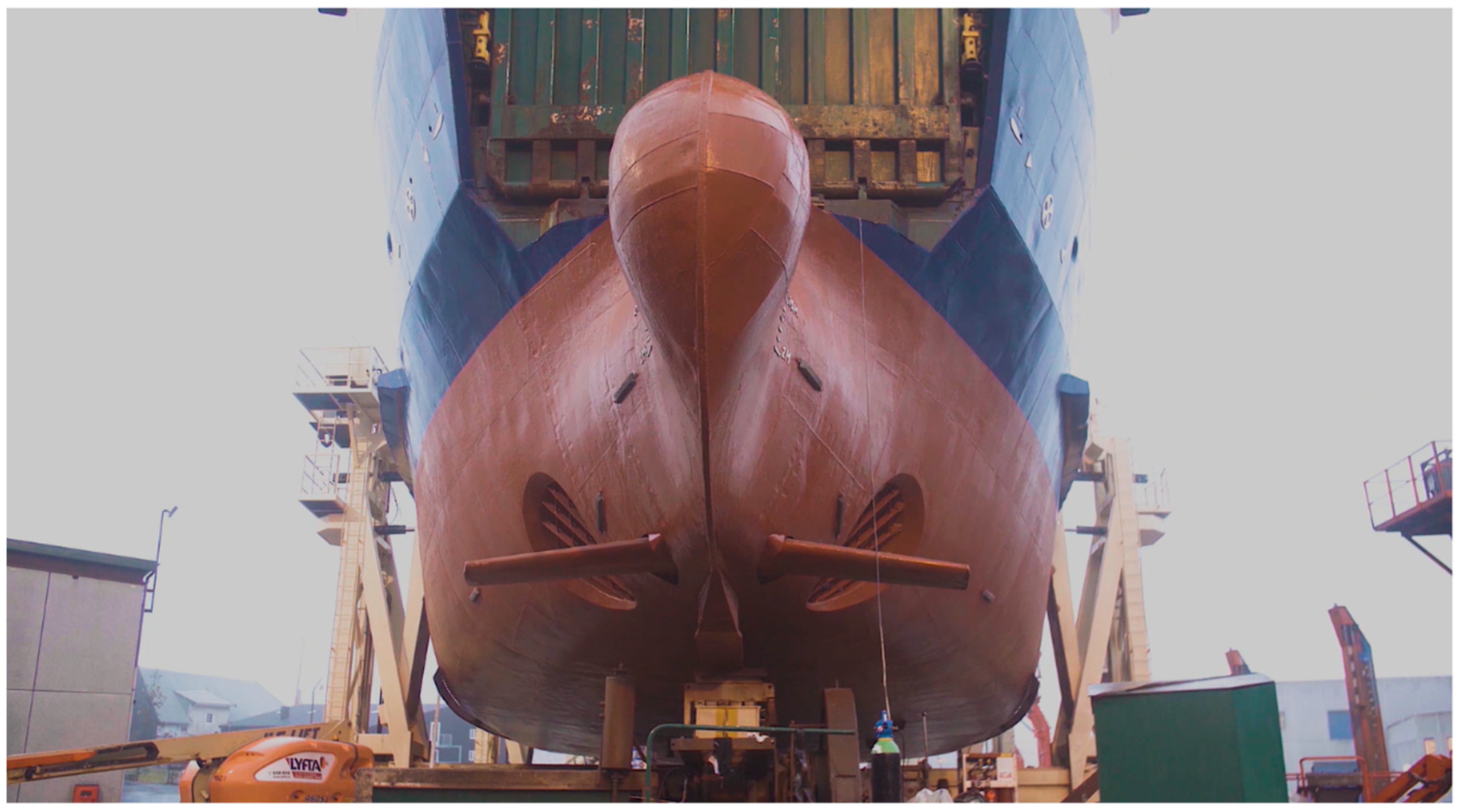
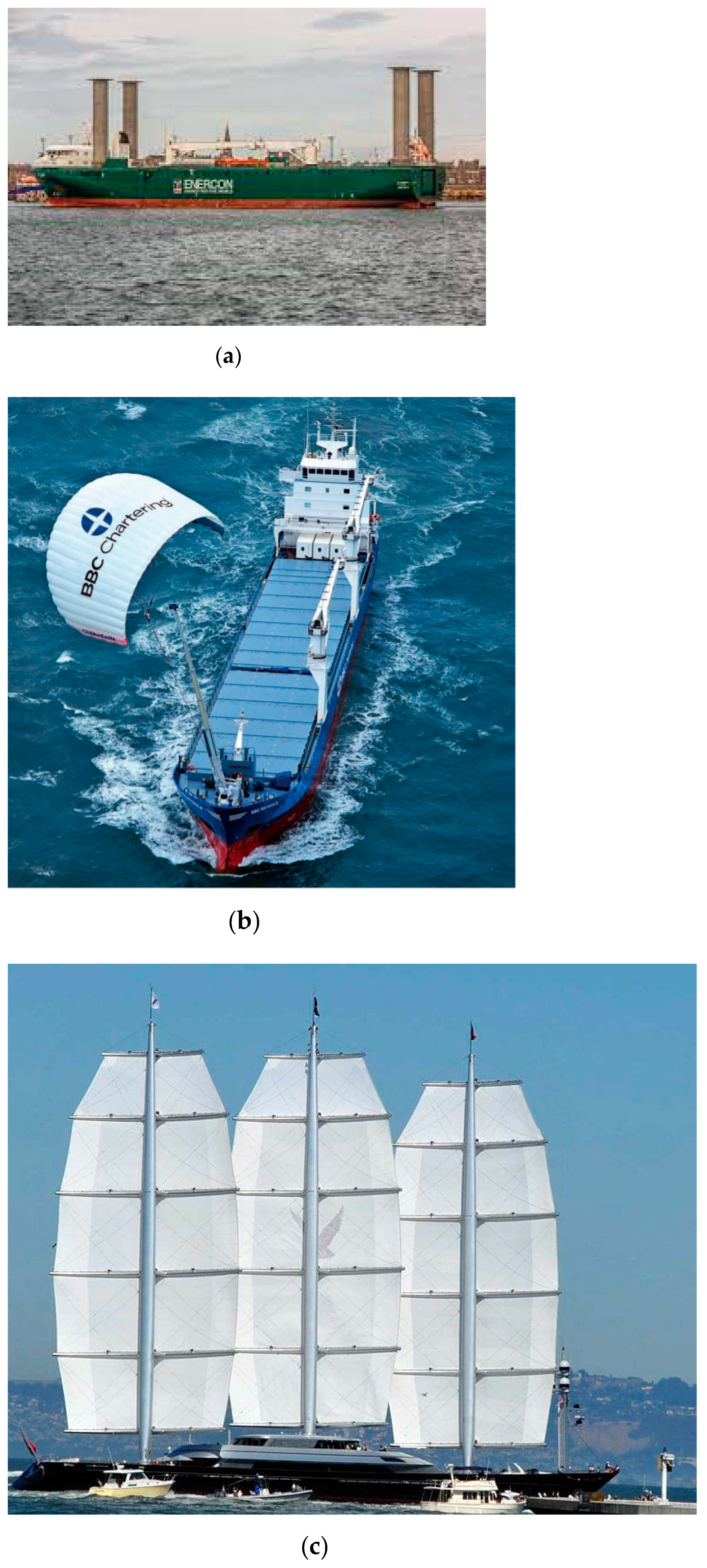
Table 1.
Summary of hydrogen-powered propulsion projects.
| Project Name | Project Description | Lead Partner | Vessel Type | Propulsion System | Timescale |
|---|---|---|---|---|---|
| Hydroville | First certified passenger shuttle that uses hydrogen to power a diesel engine | CMB.TECH | Passenger shuttle vessel | Hybrid compressed hydrogen–diesel internal combustion engine | 2016–2017 |
| HySeas (I-III) | Aims to develop the ability to employ green hydrogen as a fuel and fuel cell technology at commercial vessel scale | University of St. Andrews | Ferry | Compressed hydrogen, hybrid fuel cell—battery system | 2013–present |
| FLAGSHIPS | To deploy two commercially operated hydrogen fuel cell vessels | VTT Technical Research Centre | Commercial inland cargo transport vessel, passenger and car ferry | Compressed hydrogen, hybrid fuel cell—battery system | 2018–present (first vessel to be delivered by 2021) |
| MARANDA | Aims to use a 165 kW hydrogen proton-exchange membrane (PEM) fuel cell for auxiliary power on a Finnish research vessel | VTT Technical Research Centre | Research vessel | Compressed hydrogen hybrid fuel cell—battery system (auxiliary power only) | 2017–2021 |
| HyShip | The design and construction of a new ro-ro demonstration vessel running on liquid green hydrogen (LH2) | Wilh. Wilhelmsen Holding ASA | Ro-ro vessel | Liquified hydrogen hybrid fuel cell—battery system | 2021–2024 |
| Europa Seaways | Develop large hydrogen ferry with fuel cell capacity of 23 MW | DFDS | Ropax Ferry | Compressed hydrogen hybrid fuel cell—battery system | Vessel operational by 2027 (if successfully funded) |
| Suiso Frontier | To show liquefied hydrogen can be produced and exported safely to Japan | Kawasaki Heavy | Hydrogen Carrier | N/A, project aim to transport liquid hydrogen | First voyage to collect LH2 planned for between October 2021–March 2022 |
Table 2.
Energy density of diesel compared to different hydrogen (H) fuel states (data from [2]).
Table 2.
Energy density of diesel compared to different hydrogen (H) fuel states (data from [2]).
| Fuel Type | Diesel | Compressed H (700 bar) | Liquid H | Metal Hydride |
|---|---|---|---|---|
| Volumetric Energy Density MWh/m3 | 11.7 | 1.4 | 2.36 | 3.18 |
| Gravitational Energy Density MWh/kg | 0.0116 | 0.0333 | 0.0333 | 0.0006 |
Table 3.
Summary of ESDs and their energy saving capability and other key parameters.
| Category 1 | Category 2 | Energy Saving Device | Energy Saving (ES)/Propulsive Efficiency Increase (PEI) | Vessel Application | Additional Benefits | Technology Readiness Level |
|---|---|---|---|---|---|---|
| Hull Resistance Reduction Measures | Air Lubrication System (ALS) | 5–10% ES—sea trials | Tankers, cruise ships, ro-ro vessels | Savings independent of sea-state | 8 | |
| Hull Vanes (HV) | 15% ES—sea trials | Yachts | Improved seakeeping, dampens pitching motions, reduced wave resistance | 7 | ||
| Hull Coating (HC) | Up to 40% ES—sea trials | All | Antifouling | 9 | ||
| Bow Foils | 9%—sea trials | Ferries | Improved seakeeping, dampen ship motions | 7 | ||
| Propeller Flow Conditioning Devices | Pre-swirl Ducts | Sumitomo Integrated Lammeren Duct (SILD) | 5% PEI—sea trials | tankers, containers, bulk carriers, LNG carriers, inland vessels | Improved manoeuvring characteristics, reduction in hull vibration and the increment of cargo capacity | 9 |
| Schneekluth Duct | 12% ES—sea trials | tankers, containers, bulk carriers, LNG carriers, inland vessels | Reduced vibration, erosion, simple mounting | 9 | ||
| Mewis Duct | 7.5% ES—sea trials 6.9% ES—model-scale | Tankers, bulk carriers | Cavitation mitigation, yaw stability improvement, rpm stability improvement | 9 | ||
| Pre-swirl Fins | 10% ES—sea trials | bulk carriers, tankers | Ease of installation | 9 | ||
| Vortex Generators | 2–5% PEI—sea trials | VLCC and tanker type vessel | Reduced URN, vibration, and propeller erosion | 9 | ||
| Propeller/Hub Modifications | Propeller Modifications | NPT Propeller | 6% ES—sea trials | Container vessels, Slow steaming, bulk carriers | Reduced URN and vibrations, reduced weight | 9 |
| Kappel Propeller | 3–6% PEI—sea trials | Medium-sized container ships, tankers | Reduced URN, Better performance in off-design | 9 | ||
| CLT Propeller | 5–8% PEI—sea trials | Tankers, product carriers, ro-ro vessels, etc. | Reduced URN and vibrations, better manoeuvrability | 9 | ||
| TAPs | 6.5% PEI—model-scale CFD | Tugboats, trawlers, ro-ro vessels, tankers | Reduced URN and load fluctuation | 2/3 | ||
| Hub Modifications | PBCFs | 3–5% ES—sea trials | Container ships, etc. | Reduced URN and vibration, easy and maintenance-free installation | 9 | |
| Rudder Bulb (RB) | 2–4% ES—model-scale tests | Bulk carriers, ro-ro vessels, etc. | Hub vortex mitigation Reduced vibration and noise | 9 | ||
| Manoeuvring ESDs | Gate Rudder System (GRS) | 14% ES—sea trials | Container ships | Small drag to lift ratio Small speed drop duo to rudder angle Good manoeuvrability | 5/6 | |
| Twisted Rudders | 1–3% ES—model-scale tests | Large container ships, etc. | Mitigating rudder cavitation Reduce cavitation-induced erosion of rudder | 9 | ||
| Renewable Energy Assisted Propulsion | Wind | Rotor Sails | 5–20% ES—full-scale trials | tankers, bulkers, cruise vessels, RoRos, RoPax vessels, general cargo vessels, and ferries | Proven to withstand harsh conditions, low deck space needed compared to sails | 9 |
| Rigid Sails | 60% full-scale simulation | low uncertainties on costs of installation and maintenance, can be operated automatically | 9 | |||
| Soft Sails | 35% ES—full-scale simulations | Low weight | 7 | |||
| Wing sails | 22% ES—full-scale simulations 10% ES—sea trials | Low induced drag from device | 7 | |||
| Ventilated Foils | Lack of quantified statistics | Less space on deck occupied when compared to conventional sails | 7 | |||
| Kites | 1–50% ES—full-scale simulations | Access to high winds at greater altitudes | 7 | |||
| Wind turbine | 1–4% ES—full-scale simulations | Yachts | - | 6 | ||
| Solar | 4% ES—sea trials | Tankers, bulk carriers | - | 9 | ||
Table 4.
Potential ESD combinations for specific vessel application.
| Energy Saving Device Combination | Combined Energy Saving/Propulsive Efficiency Improvement | Vessel Application | Additional Benefits |
|---|---|---|---|
| HC-NPT-TAP-RB | Estimated at 15–25% | Ducted propulsor vessels (tugboats, fishing boats, trawlers, etc.) | Reduced URN, cavitation, load fluctuation in off-design conditions. |
| ALS-HC-WASP | Tankers, Bulkers, Cruise vessels, RoRos, RoPax vessels, General cargo vessels, Ferries | Reduced URN | |
| HV-HC-NPT | Yachts, Naval and Patrol vessels, Container ships, Ferries | Improved seakeeping and stability, reduced URN | |
| GRS-HC-NPT-PBCF | Tankers, Cargo vessels, Ferries, Container ships | Reduced URN, hub vortex strength, blade cavitation |
Publisher’s Note: MDPI stays neutral with regard to jurisdictional claims in published maps and institutional affiliations. |
© 2022 by the authors. Licensee MDPI, Basel, Switzerland. This article is an open access article distributed under the terms and conditions of the Creative Commons Attribution (CC BY) license (https://creativecommons.org/licenses/by/4.0/).
Share and Cite
MDPI and ACS Style
Stark, C.; Xu, Y.; Zhang, M.; Yuan, Z.; Tao, L.; Shi, W. Study on Applicability of Energy-Saving Devices to Hydrogen Fuel Cell-Powered Ships. J. Mar. Sci. Eng. 2022, 10, 388. https://doi.org/10.3390/jmse10030388
AMA Style
Stark C, Xu Y, Zhang M, Yuan Z, Tao L, Shi W. Study on Applicability of Energy-Saving Devices to Hydrogen Fuel Cell-Powered Ships. Journal of Marine Science and Engineering. 2022; 10(3):388. https://doi.org/10.3390/jmse10030388
Chicago/Turabian StyleStark, Callum, Yunxin Xu, Ming Zhang, Zhiming Yuan, Longbin Tao, and Weichao Shi. 2022. "Study on Applicability of Energy-Saving Devices to Hydrogen Fuel Cell-Powered Ships" Journal of Marine Science and Engineering 10, no. 3: 388. https://doi.org/10.3390/jmse10030388
Note that from the first issue of 2016, this journal uses article numbers instead of page numbers. See further details here.