
First 3D Printed IH-Type Linac Structure—Proof-of-Concept for Additive Manufacturing of Linac RF Cavities


1
Institute of Applied Physics (IAP), Goethe University, 60438 Frankfurt, Germany
2
Helmholtz Forschungsakademie Hessen für FAIR (HFHF), GSI Helmholtzzentrum für Schwerionenforschung, Campus Frankfurt, 60438 Frankfurt, Germany
*
Author to whom correspondence should be addressed.
Instruments 2022, 6(1), 9; https://doi.org/10.3390/instruments6010009
Submission received: 30 September 2021
/
Revised: 30 December 2021
/
Accepted: 26 January 2022
/
Published: 28 January 2022
(This article belongs to the Special Issue Recent Advance in Particle Accelerator Instrumentation)
Abstract
:Additive manufacturing (AM or “3D printing”) has become a powerful tool for the rapid prototyping and manufacturing of complex part geometries. Especially interesting for the world of particle accelerators is the process of the 3D printing of stainless steel (and copper) parts. We present a first prototype of a IH-type linac cavity with an internal drift tube structure manufactured by metal 3D printing. The prototype cavity has been constructed to act as a proof-of-concept for the technology. In this paper we present the concept of the cavity as well as first results of vacuum testing and materials testing.
1. Introduction
Additive manufacturing (AM) of metal parts may provide an interesting new way to manufacture accelerator components. As technology is evolving, the quality and accuracy of parts manufactured this way is ever improving. Recently, a number of studies on the topic of AM for linear accelerator components have been published [1,2,3,4]. The manufacturing of single cell GHz Nb-cavities using Electron Beam Melting was investigated by Frigola et al. in 2015. The cavities were machined and processed by BCP after manufacturing and successful cold tests were performed up to 3 MV/m [1]. Recently, there have also been efforts to investigate the material and vacuum properties of stainless steel parts made by AM for accelerator applications. An investigation of Jenzer et al. from 2017 shows the first promising results for vacuum and outgassing properties of printed beam pipes [2]. In 2019, they expanded on these results including material strength tests (AM parts show a higher yield strength than conventional 316L steel) and further vacuum investigations [3]. A short summary of efforts was published in [4]. Based on these promising results, we aim to evaluate the suitability of AM parts for direct manufacturing of normal conducting linac structures. To that end, a reproduction of the beam pipe vacuum tests in [2,3] was performed and upon success, a prototype cavity with a fully printed drift tube structure was constructed. The cavity is designed to be UHV capable and includes cooling channels reaching into the stems of the drift tube structure. In the following, the concept and first experimental results are reported. This paper is an extended version of the conference proceeding in [5], providing updated vacuum measurements and material properties investigations of the printed parts.
2. Prototype Design and Concept
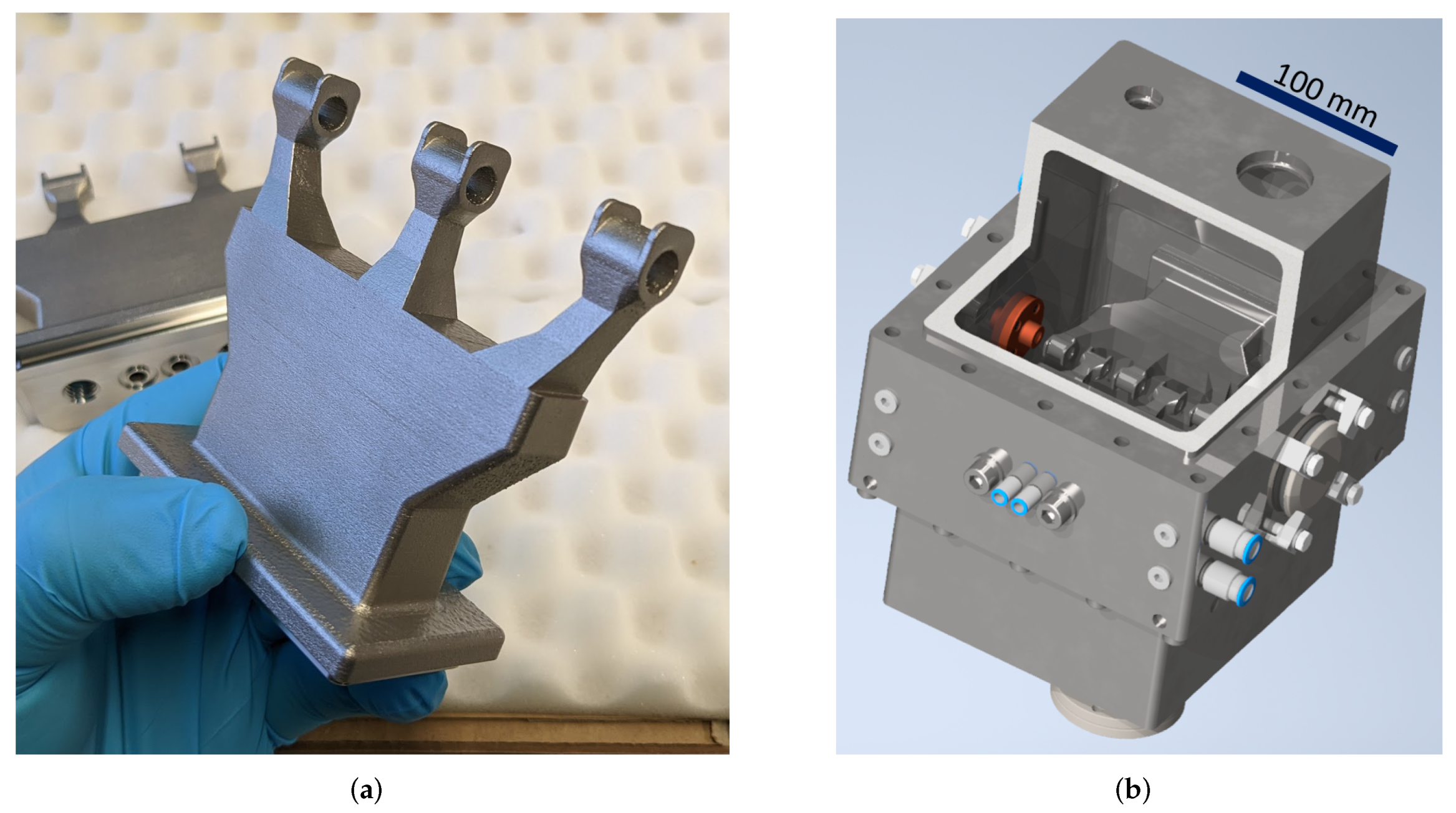
The prototype cavity was designed for a resonance frequency of , which is a harmonic of the GSI UNILAC operation frequency [6]. In combination with a targeted proton beam energy of this scenario allows for a compact accelerator at the limits of feasibility and is therefore a good benchmark for the new approach. The internal drift tube structure is fully 3D printed from stainless steel (1.4404), see Figure 1a. Due to the lower complexity of the cavity frame and lids, they are manufactured by CNC milling of bulk stainless steel.
The outer dimensions of the cavity are only 221 × 206 × (without flanges). A center frame acts as the foundation for the cavity. This 7 cm high center frame provides the precision mount points for the girder-drift tube structures and end-drift tubes. While the end-drift tubes are mounted in vacuum, the girders have a vacuum sealing surface at the bottom. Two half shells are mounted on the top and bottom of the center frame. The cavity is equipped with four CF40-Flanges for vacuum, rf-coupler and tuner, as well as KF40 flanges for the beamline and smaller ports for diagnostics. Rf simulations show that the bulk of the rf losses during the operation of this cavity is concentrated on the drift tube structure and the cavity frame. Therefore, water channels are included in the girders up to the stems and also in the center frame. A 3D CAD view of the full construction is shown in Figure 1b.
RF Simulations
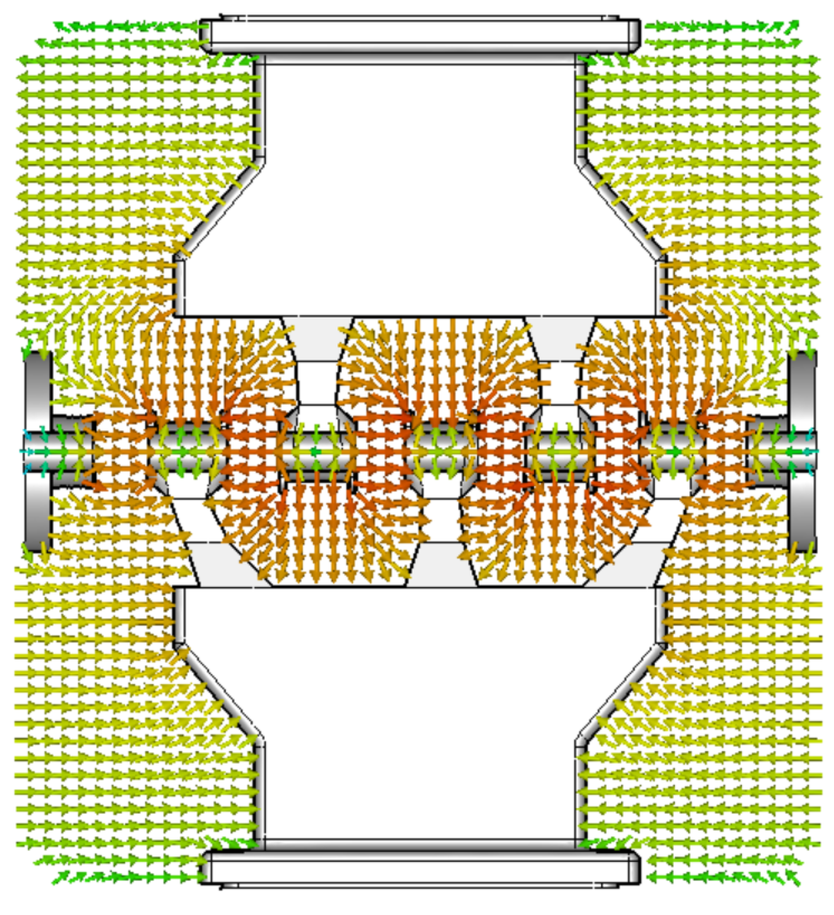
The cavity design was optimized for a frequency of 433.632 MHz. To minimize the need for support structures during the manufacturing process, the shape of the girder-drift tube structure was optimized to reduce overhang. Simulations of electromagnetic fields in the cavity were performed with the CST Microwave Studio eigenmode solver. Figure 2 shows the resulting electric field distribution in the cavity, with the typical characteristics of a IH-type structure. The simulated dissipated power for the full MV acceleration is kW, which corresponds to an effective shunt impedance of M/m. Future shape optimizations will provide opportunity for improved shunt impedance and reduced maximum fields along the structure.
3. Mechanical Accuracy
Mechanical accuracy of the printed girder-drift tube structure, especially the drift tube geometry, is critical for the field distribution in the cavity and therefore the beam dynamics. The bottom sides of the structures were milled after the printing process to provide a flat sealing surface and o-ring seals for the water channels. In the first step, however, the stems and drift tubes are not machined to evaluate the accuracy provided solely by the printing process.
While all the individual drift tube lengths and gap lengths are within an acceptable range (, see Table 1), all deviations have the same sign and therefore add up. This may be fixed by printing with excess material and shortening the drift tubes after printing using conventional machining. Another possible mitigation would be to simulate the warping of the part during manufacturing and producing a compensating model. This will be studied further, as it would reduce the necessary machining needed after printing.
4. Water Flow
Both girder-drift tube structures, as well as the center frame of the cavity are watercooled. While the watercooling in the center frame is quite conventional and realized with deep-hole drilled channels, the water cooling in the girders is more complex. To ensure, that the water channels in the girders are working as intended and not blocked by, for example, residual metal powder, some flow measurements were performed. The setup is provided with a water pressure of 8 bar. The tubing used is Festo tubing with an outer diameter of . Measurements were performed with a Kobold digital inductive flow meter. Measurement results are summarized in Table 2.
As expected, the complex inner structure of the cooling channels leads to a reduction in flow. However, the measurements show that significant cooling can be expected for these structures. Future tests with thermal loads will help quantify the cooling capabilities.
5. Preliminary Vacuum Tests
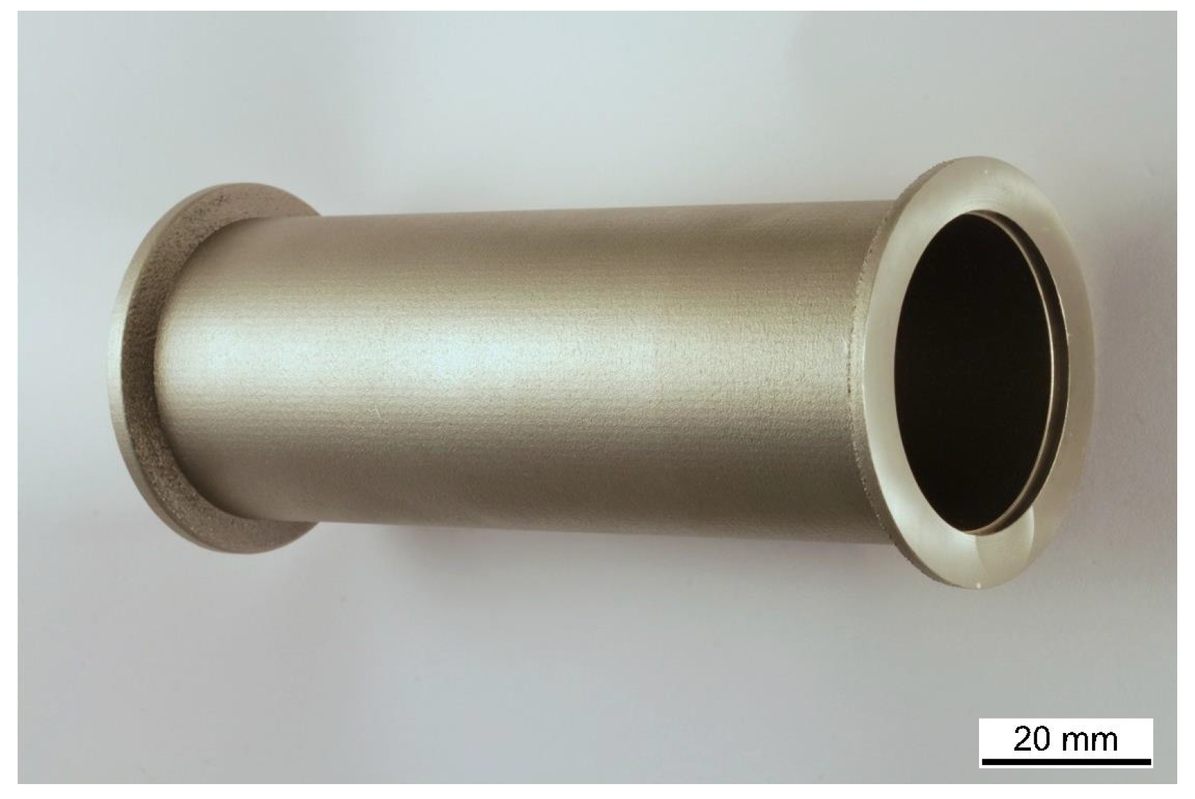
To evaluate the performance of 3D printed components in a UHV environment, preliminary tests were performed with 3D printed beam pipes with KF40 flanges (see Figure 3). These pipes were printed in 1.4404 stainless steel and the sealing surfaces on both ends were turned down on a lathe at the IAP workshop to provide a good vacuum seal. The inside and outside surfaces of the pipes were left as manufactured. A commercially available conventionally manufactured beam pipe of identical dimensions was acquired from Pfeiffer Vacuum. Both the printed and the conventional pipes were then connected to a small 18 L/s turbomolecular pump and repeatedly pumped and flushed with nitrogen gas.
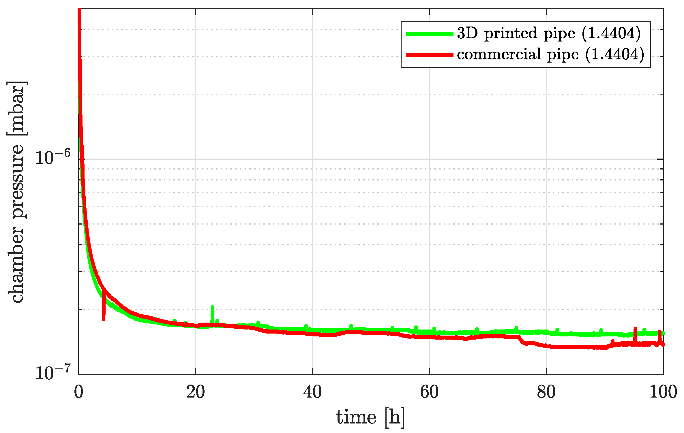
Since these pipes were not cleaned and were used as manufactured, some initial outgassing was expected. The experiment showed some interesting results. For one, as expected with each pumping and flushing cycle, the pump down time to a certain pressure point was taking less time with each iteration. In the end, both pipes performed very similar and the pumping curve as well as the achieved final pressure were indistinguishable within the accuracy limitations of the experiment. Pressure data of the fourth pumping cycle are shown in Figure 4.
The final pressure achieved was about mbar for both the conventional and the printed pipe. Similarly promising results were reported in, for example, [3,7]. These results certainly show promise for the UHV capability of printed parts. To discern more minute differences between the two samples, a test stand to accurately measure the outgassing rate via the rate-of-rise method is currently being constructed at IAP Frankfurt.
6. Printed Material Properties
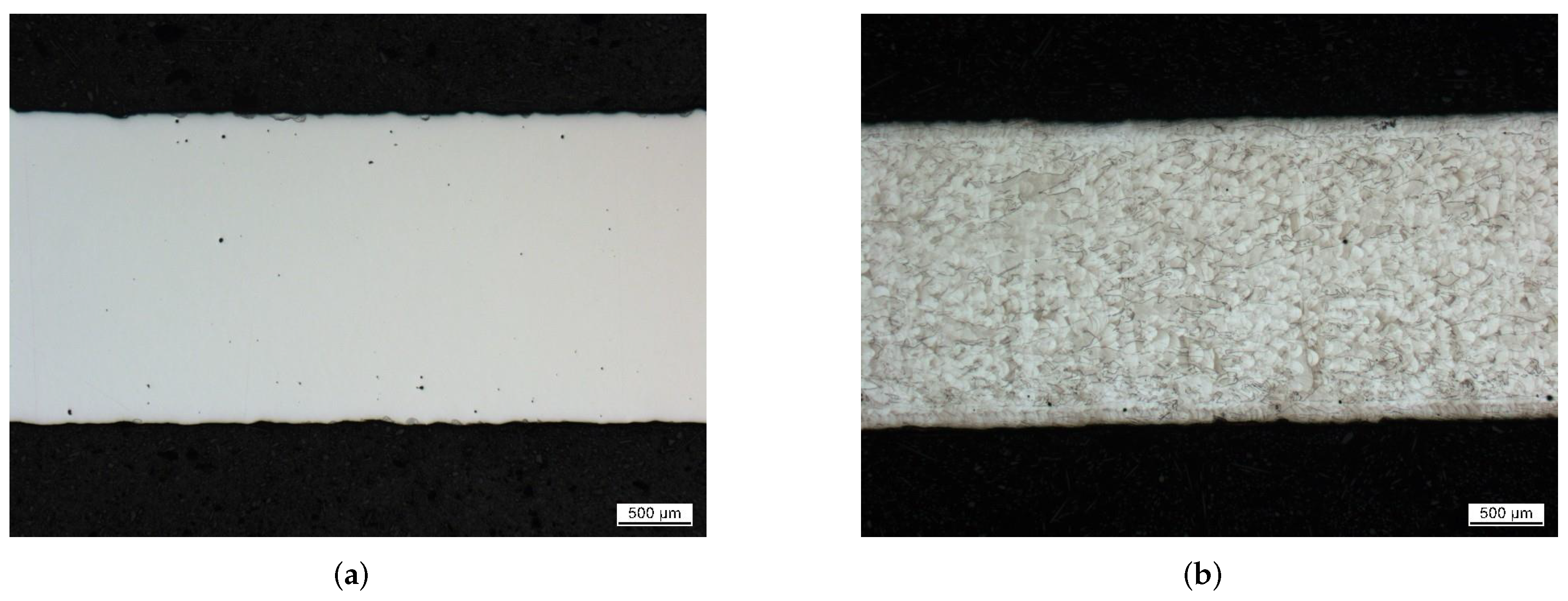
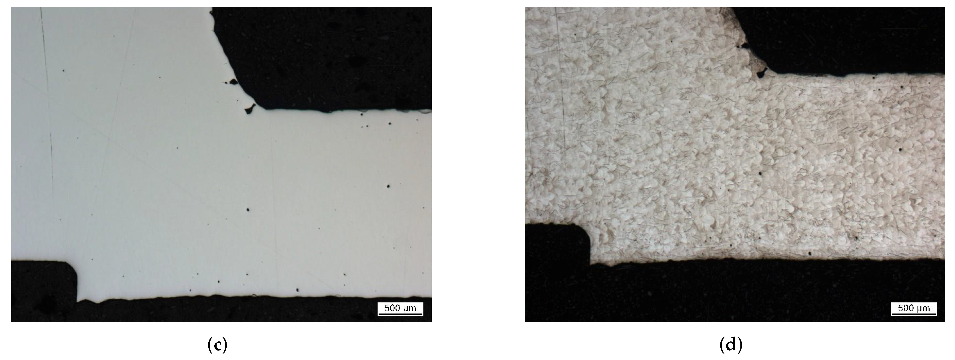
To assess the material properties, one of the printed stainless steel pipes was sent to a materials testing lab. The manufactured material was confirmed to be within the compositional limits of 1.4404 stainless steel. Surface roughness was found to be in the order of = 16.05–37.52 m dependent on location and orientation of the measurement. Material porosity was determined to be % by optical analysis of material cross-sections (see e.g., Figure 5a,c). Larger cavities in the material were found in the overhang area of the flange, but nowhere within the bulk material. The melt-pool structure of the bulk material, which is caused by the manufacturing process, can be seen in the etched cross-sections in Figure 5b,d. Overall, the material seems well suited for vacuum applications as the degree of the porosity is not concerning. Depending on the application, further surface treatment will be necessary to reduce surface roughness.
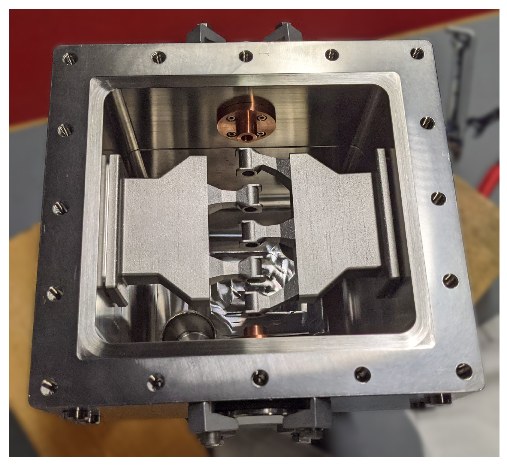
7. Cavity Vacuum Test
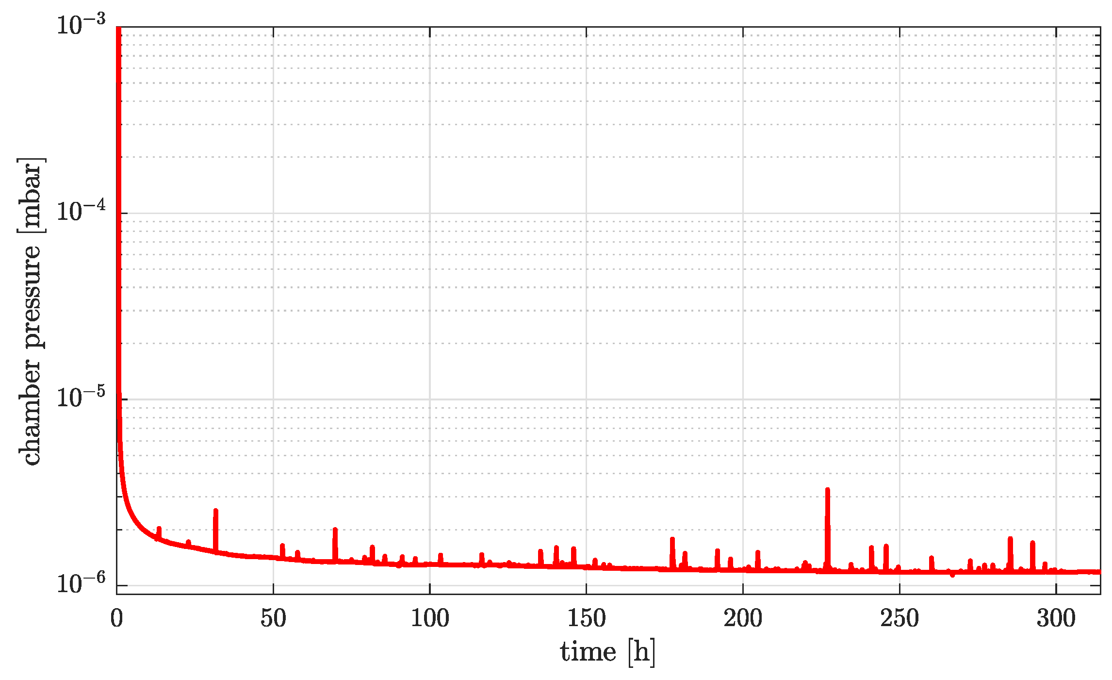
The cavity was fully assembled in early May 2021 (see Figure 6). For first vacuum tests, the cavity was attached to a turbo-molecular pump (Pfeiffer HiPace80) via one of the top CF40 flanges. A vacuum gauge (Pfeiffer PKR261) was used to measure and log the cavity vacuum. The cavity lids, as well as the girder drift tube structures were sealed using mm aluminum wire. Following the publication of [5], where a chamber pressure of was reached, the cavity was disassembled and reassembled a couple of times. An additional pump was attached via a long KF40 bellow pipe. Additional pressure gauges were attached to the cavity. Due to the addition of some new components, additional outgassing was observed during pumpdown. In the end, the result of the vacuum test was improved: At the time of writing, a pressure of was achieved after about of pumping. This latest pumpdown curve is shown in Figure 7.
While this result is already promising and the end-pressure is not reached yet, it is believed that the results can be further improved. For reliable accelerator operation, a cavity pressure of is needed. The main source for the remaining leak rates is suspected to be a minor defect in one of the conventionally milled lids of the cavity. Additional leak tests of the internal water channels in the girder drift tube structures were performed with a helium leak tester. They were found to be vacuum tight without any leakage through the bulk material of the printed structure. In the future, a second turbopump will be attached to the cavity. Additional steps will include the revision of the cavity lid sealing surface and the addition of a o-ring sealed secondary vacuum (pre-vacuum) behind the metal wire seals. Furthermore, the cavity components may also be baked to reduce outgassing.
Further Steps
In addition to the above mentioned planned improvements to the vacuum performance, the next steps will be the surface preparation and copper plating of printed components. Rf performance will be evaluated by low level rf measurements, comparing the printed parts in unpolished, polished and copper plated states. Cavity lids and center frames will also be copper plated. Finally, the structure will be tested at full power with a 30 kW pulsed rf amplifier.
8. Discussion
The first vacuum tests show promising results for this proof-of-concept cavity. A cavity pressure of mbar was reached so far. Additional tests showed that the printed structures are not a source of measurable leak rates. Mechanical accuracy of the printed parts may be improved by predictive strain simulations or after the fact machining. This prototype is a first step, indicating that stainless steel 3D printed parts can indeed be used as the main components for accelerator structures. This opens up many possibilities for more complex designs and possibly previously impossible geometries for particle accelerators.
Author Contributions
Conceptualization, H.H. and U.R.; methodology, H.H. and U.R.; software, H.H.; writing—original draft preparation, H.H.; writing—review and editing, H.H. and U.R.; visualization, H.H.; project administration, H.H.; funding acquisition, H.H. and U.R. All authors have read and agreed to the published version of the manuscript.
Funding
This research was funded by Bundesministerium für Bildung und Forschung grant number 05P21RFRB2.
Acknowledgments
The authors would like to acknowledge the contribution of material analysis of printed parts, which was organized and funded by the GSI Darmstadt proton linac project team.
Conflicts of Interest
The authors declare no conflict of interest.
References
- Frigola, P.; Agustsson, R.B.; Faillace, L.; Murokh, A.Y.; Ciovati, G.; Clemens, W.A.; Dhakal, P.; Marhauser, F.; Rimmer, R.A.; Spradlin, J.K.; et al. Advance Additive Manufacturing Method for SRF Cavities of Various Geometries. In Proceedings of the 17th International Conference on RF Superconductivity (SRF’15), Whistler, BC, Canada, 13–18 September 2015; pp. 1181–1184. [Google Scholar]
- Jenzer, S.; Alves, M.; Delerue, N.; Gonnin, A.; Grasset, D.; Letellier-Cohen, F.; Mercier, B.; Mistretta, E.; Prevost, C.; Vion, A.; et al. Study of the Suitability of 3D Printing for Ultra-High Vacuum Applications. In Proceedings of the 8th International Particle Accelerator Conference (IPAC’17), Copenhagen, Denmark, 14–19 May 2017; pp. 3356–3358. [Google Scholar] [CrossRef]
- Sattonnay, G.; Alves, M.; Bilgen, S.; Bonnis, J.; Brisset, F.; Gonnin, A.; Grasset, D.; Jenzer, S.; Letellier-Cohen, F.; Mercier, B.; et al. Is it Possible to Use Additive Manufacturing for Accelerator UHV Beam Pipes? In Proceedings of the 10th International Particle Accelerator Conference (IPAC’19), Melbourne, Australia, 19–24 May 2019; pp. 2240–2243. [Google Scholar] [CrossRef]
- Delerue, N.; Carduner, H.; Gerard, R.L.; Jenzer, S.; Manil, P.; Repain, P.; Simar, A. Prospects of Additive Manufacturing for Accelerators. In Proceedings of the 10th International Particle Accelerator Conference (IPAC’19), Melbourne, Australia, 19–24 May 2019; pp. 4118–4120. [Google Scholar] [CrossRef]
- Haehnel, H.; Ratzinger, U. First 3D Printed IH-Type Linac Structure—Proof-of-Concept for Additive Manufacturing of Linac rf Cavities. Presented at the 12th International Particle Accelerator Conference (IPAC’21). Campinas, Brazil, 24–28 May 2021. [Google Scholar] [CrossRef]
- Ratzinger, U. The New High Current Ion Accelerator at GSI and Perspectives for Linac Design Based on H-Mode Cavities. In Proceedings of the 7th European Particle Accelerator Conference (EPAC’00), Vienna, Austria, 26–30 June 2000. [Google Scholar]
- Wolf, C.R.; Beck, F.B.; Franz, L.; Neumaier, V.M. 3D Printing for High Vacuum Applications. In Proceedings of the 22nd International Conference on Cyclotrons and Their Applications (Cyclotrons’19), Cape Town, South Africa, 22–27 September 2019; pp. 317–320. [Google Scholar] [CrossRef]
Figure 1.
Overview of the cavity geometry and printed parts. (a) 3D printed girder drift tube structure. (b) Cross section of the assembled cavity model.
Figure 1.
Overview of the cavity geometry and printed parts. (a) 3D printed girder drift tube structure. (b) Cross section of the assembled cavity model.

Figure 2.
Electric field distribution in the prototype cavity.

Figure 3.
KF 40 pipe printed from stainless steel.

Figure 4.
Pumpdown curve of the fourth vacuum cycle of the KF40 test pipes.

Figure 5.
Cross sections of printed KF40 pipe. (a) material homogeneity of the pipe wall (untreated cut); (b) material structure of the pipe wall (etched cut); (c) material homogeneity of the flange overhang (untreated cut); (d) material structure of the flange overhang (etched cut) Courtesy of GSI Darmstadt, pLinac project.


Figure 6.
Top view of the cavity during assembly with installed drift tube structure.

Figure 7.
Pumpdown curve of the fully assembled cavity.


Table 1.
Deviation of Measured Dimensions from the Original Design Values.
| Girder 1 | Girder 2 | ||
|---|---|---|---|
Table 2.
Waterflow Measurement.
| Scenario | Water Flow |
|---|---|
| Source | L/min |
| 6 mm tubing | L/min |
| Girder 1 | L/min |
| Girder 2 | 5 L/min |
| Girder 1&2 parallel | L/min |
Publisher’s Note: MDPI stays neutral with regard to jurisdictional claims in published maps and institutional affiliations. |
© 2022 by the authors. Licensee MDPI, Basel, Switzerland. This article is an open access article distributed under the terms and conditions of the Creative Commons Attribution (CC BY) license (https://creativecommons.org/licenses/by/4.0/).
Share and Cite
MDPI and ACS Style
Hähnel, H.; Ratzinger, U. First 3D Printed IH-Type Linac Structure—Proof-of-Concept for Additive Manufacturing of Linac RF Cavities. Instruments 2022, 6, 9. https://doi.org/10.3390/instruments6010009
AMA Style
Hähnel H, Ratzinger U. First 3D Printed IH-Type Linac Structure—Proof-of-Concept for Additive Manufacturing of Linac RF Cavities. Instruments. 2022; 6(1):9. https://doi.org/10.3390/instruments6010009
Chicago/Turabian StyleHähnel, Hendrik, and Ulrich Ratzinger. 2022. "First 3D Printed IH-Type Linac Structure—Proof-of-Concept for Additive Manufacturing of Linac RF Cavities" Instruments 6, no. 1: 9. https://doi.org/10.3390/instruments6010009