
Seismic Performance of Panel Connectors with Steel Frame Based on Autoclaved Lightweight Concrete (ALC)


1
College of Civil Engineering, Anhui Jianzhu University, Hefei 230601, China
2
Architecture and Civil Engineering, City University of Hong Kong, Hong Kong 999077, China
*
Author to whom correspondence should be addressed.
Buildings 2022, 12(3), 372; https://doi.org/10.3390/buildings12030372
Submission received: 28 January 2022
/
Revised: 26 February 2022
/
Accepted: 15 March 2022
/
Published: 17 March 2022
(This article belongs to the Special Issue Advances in Design and Disaster Mitigation of Engineering Structures)
Abstract
:This paper proposes new prefabricated autoclaved lightweight concrete (ALC) connectors which allow limited sliding. The seismic performance of the proposed connectors and a traditional connector (L-hooked bolt) were investigated in depth. Three specimens of full-scale steel frames with ALC panel and connectors were subjected to horizontal low-cyclic loading. The failure modes, hysteretic behavior, strength and deterioration of stiffness and energy-dissipating performance of all specimens were analyzed and discussed. The experimental results indicated that the frames of the new connectors were more reliable than the traditional connector. The energy-dissipating capacity of the specimen frames with new connectors increased by 23.0% and 24.4%, and deterioration of stiffness increased by 10.6% and 13.0%. The new ALC panel connectors not only increased elastic stiffness in the early stage, but also provided some stiffness in the elastoplastic and plastic stages. Using relevant construction measures, the frames with new connectors displayed good cooperative behavior and safety reliability. To summarize, the new ALC connectors tested showed excellent performance in resisting seismic loading and had good assembly efficiency and could provide a basis for the development and application of a new type of ALC steel frame connector.
1. Introduction
Prefabricated structure is a form of modern industrial building structure. Compared to cast-in-place structure, it has advantages of convenient construction, less wet work on site, lower cost, energy saving and environmental protection [1,2,3]. With the rapid development of building industrialization, prefabricated reinforcement structures have been widely used in many countries [4]. Autoclaved lightweight concrete (ALC) panel has advantages of light weight, heat insulation, sound insulation, fire protection, energy saving and environmental protection, and easier curing than traditional concrete, and has been widely used in prefabricated reinforcement structures [5,6,7,8]. Therefore, the use of ALC panel in the enclosure walls of steel structure buildings is increasing by the day. At present, research on ALC panels mainly focuses on their performance, including the stress of the panel with a multi-layer H-shaped light steel structure. Qu carried out structural testing and numerical simulation of four ALC panels, using ABAQUS to simulate the test panels [9]. Zhang Guowei carried out four-point loading tests on ALC panels, finding that ALC panel damage occurred mainly in the 45° zone, near the joints, in panel-panel and frame-panel areas [10]. De Matteis and Llandolfo carried out numerical simulation of a steel frame structure with cladding light wall panels. The results showed that steel consumption in low earthquake zones could be reduced by 20%, while ensuring stability, by replacing the support system with wall panels [11]. The connector between the ALC panel and the main structure is a critical part in the steel structure; its performance directly affects the stiffness, stability and bearing capacity of the structural system [12,13]. Wang Bo conducted low-cycle repeated loading tests of ALC panel or block-filled CFST frame structures. It was demonstrated that u-shaped steel clamps, swing joints and angles were necessary to ensure that frames could work well under seismic action (in accordance with the requirement of the plastic limit displacement angle: 1/50) [14]. In the process of using the wall panel and the steel frame cladding connector, not only should the structure be firmly connected, but the deformation of the two parts should also be coordinated under several kinds of impact. If the connector is broken during an earthquake, the wall panel will fall off and cause serious secondary disasters [15].
In China, there is little research on the connection of cladding panels—the main connection method used is the hook bolt. Although the hook bolt is easy to assemble, and is seismically resistant when the panel is not deformed greatly, the bolts are connected to a steel angle which is welded to the steel beams through an opening that penetrates the wall. During long periods of suspension or seismic loading, the hole will be damaged, which will reduce the connection between the panels and even cause the panels to fall off [16,17]. Although the Nanjing Xujian Company innovated a kind of wall panel connection connector for NALC panels, it requires special processing in the factory, and mortar needs to be poured on site—in contradiction to the prefabricated building approach currently being promoted [18]. Cao Shi et al. evaluated a new type of ALC connector, which consists of steel angle, stiffening floor, and embedded parts of the wall panel. The experimental results showed that the new type of node had good mechanical properties and broad potential practical application [19]. The embedded node compensates for the defect of the bolt connection of the hook head to some extent, but its structure is intricate, field installation speed is slow, and cost is high. In addition, errors in production, construction and transportation may lead to size changes, resulting in insufficient precision, preventing utilization [20,21].
In order to solve the above problems, based on our previous work, two new types of ALC connectors were proposed. In these, the ALC panel is supported from the bottom by a new connector instead of being hooked by a traditional L-hooked bolt; at the same time, the sliding holes are reserved to offset the seismic load. This kind of connector overcomes some of the defects of the existing connector and has advantages of no wet work, simple structure, convenient construction, high construction speed and good seismic performance. To guarantee the reliability of the connector, experimental investigations of full-scale steel frame models incorporating two panel connection types subjected to low cyclic reversed load test were conducted.
2. Details of Research
2.1. Connector Design
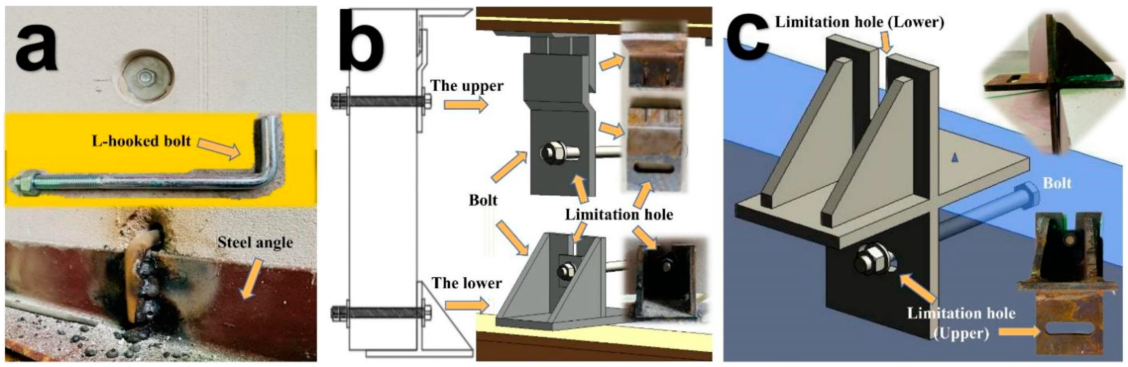
When a building structure has a large lateral shift, damage to panels can be reduced depending on their sway which is driven by the node. Therefore, two new types of connectors were designed to enable the ALC panel and steel frame to connect stably to form an integrated structural system, such that deformation due to external forces can be managed. The design of the connectors followed the design concept of “keep stable in small earthquakes, can be repaired after medium earthquakes, and no collapse in a large earthquake” [22]. The traditional L-hooked bolt is connected by angles which are as long as a steel beam, so high temperature in one place quickly affects the functioning of the whole ALC wall. This creates high risk of fire. However, the new connector is an independent component applied to the whole ALC wall. This means that, in a fire environment, even if one part suffers from high temperature, it will not immediately affect the working condition of other connections.
The new ALC crossing panel connector combines load-bearing holes and limitation holes to form a cross-shaped connector. It includes an I-beam, an ALC panel, a cross-shaped connector, a bolt and a nut. The new ALC pendulous Z-panel connector can be divided into an upper node and a lower node. An I-beam, ALC panel, full-length steel angle, common bolts and nuts, and a Z-node panel are the main components.
In order to facilitate installation, a slotted hole is opened in the upper part of the connector as the lower load-bearing node of the upper exterior wall panel, which bears the vertical, outward horizontal and inward horizontal loads of the upper exterior wall panel; a long circular hole is opened in the lower part of the connector in the horizontal direction, with a hole diameter slightly larger than the diameter of the bolt; the type of upper bolt hole is a long circle hole, which allows a sliding displacement of 75 mm. As the upper limit node of the lower exterior wall panel no longer bears the load in the inward horizontal direction, it can enable the panel and the main structure to work together. The ALC panel connectors are shown in Figure 1.
2.2. Experimental Design
Full-sized steel frames were selected for the low cyclic reversed load tests. According to the standards for residential building height, column span, beam and column section size, the final design for a story height of 3000 mm, requires a 3400 mm single span plane steel frame. In this test, there were three sets of specimens connected to the panel and the main frame, respectively, as shown in Table 1.
All specimens were prefabricated at the factory according to dimensional requirements. The panels were ALC panels, of dimensions, 600 mm wide, 200 mm thick and 3000 mm high. The wall was made of five external ALC panels, and the seams of the panels were made of ALC panel special patchwork binder. The length of the L-hooked bolt was 200 mm and the specification was M12. The beams were designed as HM244 mm × 175 mm × 7 mm × 11 mm, beam length 3800 mm; the column was designed as HW200 mm × 200 mm × 8 mm × 12 mm, column height: 3888 mm. The connectors were Q345, and the other steel members were Q235 hot-rolled H-beams; the ALC panels were A3.5 B05 standard [23]. After all the specimens were produced and maintained, they were then delivered to and assembled on the test site. The setup process and overview of the test specimens are shown in Figure 2 and Figure 3 below.
2.3. Experimental Facility and Setup
In this test, an American MTS servo-loading system with actuator displacement stroke of 500 mm was used. In this experiment, a quasi-static loading scheme was adopted in which a horizontal, low-cycle reciprocating load was applied to the top of the column, and the top panel of the column was connected with the hydraulic servo actuator. The test loading device is shown in Figure 4.
As illustrated in Figure 5, the experimental loading device consisted of an electro-hydraulic servo-loading system, hydraulic jack, hydraulic actuator, connecting rod, anchor bolt, and reaction frame. For the loading test, the electro-hydraulic servo loading system was attached to the actuator.
2.4. Material Properties
Six 100 mm × 100 mm × 100 mm and three 100 mm × 100 mm × 300 mm ALC cube test blocks were poured under the same conditions, as shown in Figure 6. All samples were manufactured and maintained under the same conditions, according to “The test methods for autoclaved aerated concrete” (GB/T 11969-2020) [24]. For the steel properties, steel coupons, according to GB/T 228.1-2010 [25], were cut from steel tubes and sheets and assessed to determine the tensile strength, modulus of elasticity, as well as breaking elongation. Table 2 shows the results of the steel material tests. Table 3 shows the ALC panel mechanical performance index.
2.5. The Experiment Loading System
For loading, the displacement control method was used. Figure 7 illustrates the loading system. After yielding, displacement was applied, the process was repeated three times for each displacement. The push-down was positive, while the pull-up was negative. According to the inter-story displacement angle index of the GB50011-2010 “Code for Seismic Design of Buildings” [26], the limit value of the interlayer displacement angle for light and medium earthquakes is 1/250, while the limit value of the interlayer displacement angle for rare earthquakes is 1/50.
The test was preloaded with 2 mm, loaded for three turns, to ensure that the steel frame loading version and the splice gap of the booster were fully adjusted. Then the load was controlled by the displacement angle, where the maximum displacement angle was 3/10 (90 mm). Three turns were loaded at each stage before 1/250, 1/600, 1/500, 1/400, 1/350 and 1/300 cycles, and two turns were loaded at each stage afterwards (1/250, 1/200, 1/100, 1/75, 1/50, 1/40, 3/10 cycles).
3. Experimental Results
3.1. Specimen SFW1
Specimen SFW1 was a traditional L-hooked bolt which connects to the external ALC panel with a steel frame. When the displacement angle reached 1/500 (±6 mm cycle), cracks appeared in the joint mortar at the bottom of the No.1 and No.2 panel joints, as shown in Figure 8a. When the displacement angle was between 1/300 and 1/250 (±10–12 mm cycle), small fragments of ALC panels were constantly falling off, caused by the pressure between the panels, as shown in Figure 8b. When the displacement angle reached 1/200 (±15 mm cycle), there was obvious dislocation between the panels which had fallen off the patchwork joints, which made a sliding sound between the retaining steel bars and the edge of the panel, as shown in Figure 8c. When the displacement angle reached 1/75 (±40 mm cycle), angle steel welds on the upper part of No.2 panel broke, and in the hole of the L-hooked bolt under No.3 panel an extended crack appeared, as shown in Figure 8d,e. When the displacement angle reached 1/40 (±75 mm cycle), the L-hooked bolt became flexible and started swinging, the corners of each panel broke, and at the holes of the L-hooked head bolts under No.4 and No.5 panel extended cracks appeared. Meanwhile, the holes of the bolts began to expand, the bolts swinging with the steel angle as the displacement was applied, as shown in Figure 8f,g. When the displacement angle reached ±90 mm, the left upper beam-column joints made a loud sound because of fracture of the weld, as shown in Figure 8h.
3.2. Specimen SFW2
Specimen SFW2 was the new crossing panel connector. In the process of loading to the displacement angle 1/100 (±30 mm cycle), a friction sound between the enclosure reinforcement and the end panel occurred. There was still no significant change in the frame and panel, although the bolt at the upper panel connector slipped within its bolt hole, implying that the follower performance of the junction was quite good, as shown in Figure 9a. When loading to 40 mm, small pieces of debris came off, and the corner of the panel behind panel No. 5 was broken, as shown in Figure 9b. When loading to 60 mm, the maximum limitation of the limitation hole was reached, the stiffness significantly increased. the splicing mortar between No.1 and No.2 panels broke, cracks appeared in the lower left corner panel corner of No.1 panel, cracks appeared in the back panel corner of No.2 panel with steel frame, and the relative movement between No.1 and No.2 panels could be seen, as shown in Figure 9c. When loading to 75 mm, cracks appeared at the upper bolt holes of No.2 and No.3 panels, and the lower node of the second panel was loose. Obvious interpanel dislocation could be seen, as shown in Figure 9d,e. At 90 mm loading, the mortar of the joints collapsed between No.2 and No.3 and No.3 and No.4 panels, and the corner of the back of the No.1 panel was broken off, as shown in Figure 9f.
3.3. Specimen SFW3
Specimen SFW3 was the new pendulous Z-panel connector. Before test loading to the displacement angle 1/250 (±12 mm cycle), there was no obvious change in the frame and no cracks appeared in the panel. However, the bolt at the upper panel connector slipped within its bolt hole, which made a friction sound, indicating that the slipping mechanism of the panel connector did work, as shown in Figure 10a. When the displacement angle reached 1/200 (±15 mm cycle), a vertical crack appeared in the bottom of the No.2 panel, as shown in Figure 10b. When the displacement angle reached 1/100 (±30 mm cycle), cracks in the bottom of No.2 panel extended, and the back corner of No.4 panel broke, as shown in Figure 10c, because of the further enhancement of the panel-panel displacement. When the displacement angle reached 1/75 (±40 mm cycle), the bonding mortar between No.1, No.2 and No.4 and No.5 cracked. A small amount of shedding of fragments, as shown in Figure 10d, occurred. When the displacement angle reached 1/40 (±75 mm cycle), extended cracks at bolt holes in No.1. Obvious dislocation between panels could be seen, shown in Figure 10e. At 60 mm displacement angle, the maximum limitation of the limitation hole was reached, and stiffness was significantly increased. When the displacement angle reached 90 mm, new vertical cracks appeared in the bottom of the No.2 panel, and the fragments of back corners of No.3 and No.4 panels fell off, as shown in Figure 10f,g.
4. Discussion
4.1. Load-Displacement Hysteretic Behavior
Measured cyclic response curves (hysteretic curves) obtained from all specimens are given in Figure 11. With increasing column end displacement, the overall stiffness degradation and the strength degradation of SFW1 at the same level loading were observed; the same phenomenon occurred with SFW2 and SFW3, though this was relatively less obvious when compared to SFW1. This was mainly attributed to: the frame gradually moving from the elastic stage to the elastic-plastic and plastic stage, mortal splitting between ALC panels or blocks, cracking and crushing on the ALC panels plastic deformation, and welding fracture at the beam-to-column connections and wall-to-frame connections, which resulted in composite frame destruction and partial transmission of mutual forces. The reason why this was less obvious for SFW3 was that the new connectors gave more stiffness to the frame and did not allow it to go through the elastic-plastic and plastic stages for a loaded displacement of 90 mm, as occurred with SFW1.
The hysteresis curves of all three types of ALC panel connected frames were inverse S-shaped. As shown by B. Wang [14], the contribution of the facade to the antiliteral load is greater than that of the pure steel frame. At the same displacement level in the late stage, the load carrying capacity of the cross-panel connector group and the pendulous Z panel connector group (specimens SFW2 and SFW3) was greater than that of the L-hooked bolt group (specimen SFW1). More importantly, specimen SFW1 was more brittle than specimens SFW2 and SFW3 in terms of the experimental evaluation of stiffness degradation and strength degradation, under the same horizontal load. This was due to the fracture of the weld between the L-hooked bolt group (SFW1) and the angle at the 75 mm stage, which resulted in degradation in stiffness and loss of load-carrying capacity after 75 mm, although its load-carrying capacity was previously higher than the other groups. In contrast, specimens SFW2 and SFW3 were in swaying energy dissipation in the early stage (before 30 mm) and provided higher stiffness and load capacity for the frame in the later stage due to the restricted displacement of the slip on the bolt hole.
4.2. Skeleton Curve
The skeleton curve connecting the peak points of each cyclic loading curve of the hysteresis curve of the structure and members reflects the link between peak loads and corresponding displacements from the specimen’s hysteresis loops, such as the characteristics of the different stages of force and deformation of the specimens. As can be seen from Figure 12, the trends in the skeleton curve of the three groups of specimens were basically the same. Each specimen experienced the three stages of elasticity, elastomer-plasticity and damage. The skeleton curves were approximately S-shaped, and the trend in stiffness degradation was more obvious.
In the early stage (5–40 mm cycle), the trends in the skeleton curves of the three groups basically overlapped. SFW1 was larger than SFW2 and SFW3, indicating that both specimens were in the elastic stage. However, because the bolts of the new connectors of SFW2 and SFW3 slid in the limitation holes with loading, their load capacity and stiffness were less than that of the L-hooked bolt connector (SFW1), which means the new connector effectively released the energy. In the intermediate stage of the test (40–75 mm cycle), the partial rigidity of the new connector (SFW2 and SFW3) was only demonstrated after the displacement of the new connector bolt at the limitation hole had reached its limit. Due to the rigid connection of SFW1 entered the yielding stage first, the rise in the load-carrying capacity of SFW1 became flat as the displacement loading was exceeded by SFW2 and SFW3. At this point, the new connectors (SFW2 and SFW3) started to contribute stiffness to the frame, making the frames’ load capacity higher. During the later 75–90 mm cycle stage, each of the specimens was in the yielding stage. The curve for SFW1 fluctuated suddenly, then rapidly started to decrease to a value much smaller than those for SFW2 and SFW3. This was because as the weld of the L-hooked bolt (SFW1) with the angle steel broke at 75 mm loading, the connection type of SFW1 became too flexible overall, and the stiffness contribution of the frame decreased rapidly. The bearing capacity of the L-hooked bolt started to reach its peak, then rapidly entered the damage phase, which was obviously smaller than for the situation with SFW2 and SFW3. The connection types of specimens by displacement loading is show in Table 4.
Table 5 summarizes characteristic yielding and peak points of specimens based on envelope curves. Three typical characteristic points were introduced in accordance with Figure 12 shown in the JGJ/T 101-2015 [27]. Point 1 represents the yield point and point 2 shows the ultimate load and corresponding displacement of the composite structure. With the benefit of the sliding holes of the new connections, the yield loads of SFW2 and SFW3 increased by 13.8% and 10.6% compared to SFW1, respectively. The maximum bearing capacity of specimen SFW1 decreased by 8.9% compared to specimen SFW2 and decreased by 13.3% compared to specimen SFW3. In terms of yield displacement, SFW2 and SFW3 were delayed by 13.6% and 12.7%, respectively. With respect to ultimate displacement, SFW2 and SFW3 were delayed by 22.7% and 30.0%, respectively. This showed that the new ALC panel connectors (SFW2 and SFW3) not only increased elastic stiffness in the early stage, but also provided some stiffness after the early stage, with enhanced ultimate bearing capacity compared to SFW1. The results indicated that the new ALC panel connectors (SFW2 and SFW3) greatly improved the bearing capacity and stiffness of the composite frame when compared to the L-hooked bolt (SFW1).
4.3. Deterioration in Stiffness
Stiffness degradation is another metric for describing the seismic behavior of structures [28]. Stiffness steadily deteriorates as the lateral drift in the quasi-static test load increases—this degradation is typically regarded as a critical index for determining the extent of structure collapse. In this investigation, the equivalent stiffness method was used to characterize the stiffness of the connectors. Equivalent stiffness is given by the slope of the line connecting the maximum value of the reaction force (positive and negative) of each step of loading. The secant stiffness of each frame during the mean value of cycles of each amplitude loading is shown in Figure 13. The formula for secant stiffness is as follows:
As for the 40 mm cycle, the deterioration in stiffness of SFW2 and SFW3 appeared to increase briefly because the bolts of the new connectors reached the limitation of the limit holes. This was also the reason that the initial deterioration in stiffness of SFW2 and SFW3 was slower than SFW1 during the beginning of loading. As for the 40 mm cycle, the deterioration in stiffness of SFW2 and SFW3 appeared to increase briefly because the bolts of the new connectors reached the limitation of the limit holes. Then, in the 60–90 mm stage, the deterioration of stiffness of SFW1 decreased sharply, while the SFW2 and SFW3 were relatively flat and exceeded SFW1 at 60 mm. The averages of the three groups of deterioration of stiffness after the elastic stage were 2.15, 2.38 and 2.43, respectively. Compared to the traditional L-hooked bolt (SFW1), SFW2 increased by 10.6% and SFW3 increased by 13.0%. This indicated that the bearing capacity of the new ALC connectors was larger than for the L-hooked bolt. The new ALC connectors showed good stiffness characteristics.
4.4. Energy Dissipation
The dissipation energy capacity of the structure at the drift angle was measured by the area of stress to strain enclosed. The energy dissipation capacity of the structure is closely related to the area of the hysteresis loop [29]. The more the structure dissipates energy, the safer the structure and the less likely it is to be damaged.
The equivalent damping factor (ξe) was defined by Equation (2) [30]. The area diagram is shown in Figure 14. The area surrounded by the ABCF curve is the energy dissipation capacity of the structures.
The energy dissipation parameters of specimens at ultimate state are listed in Table 6. The total dissipation energy Wtotal is defined as the areas of the hysteresis curves when specimens are under ultimate state. The energy dissipation capacity of the specimen is expressed by the energy dissipation factor DE. The energy dissipation coefficient DE can be defined as:
The energy-dissipating capacity (DE) of specimens is shown in Figure 15. This shows the equivalent damping factor (ξe) versus the relative horizontal displacement relationship of the specimens. The overall trend of the curves was that the equivalent damping factor (ξe) of SFW1 reduced rapidly with increasing relative displacement (0–10 mm), then increased rapidly (after 10 mm). The new connectors (SFW2 and SFW3) also showed this phenomenon, except with a delay starting in a slow decline until 40 mm, and a rapid raise after 60 mm. The difference was that the equivalent damping factor (ξe) of SFW2 and SFW3 rose quickly in the 0–40 mm stage because the bolts of the new connectors were dissipating energy by sliding in the limitation holes. At a displacement less than 52.7 mm, the equivalent damping factors (ξe) of SFW2 and SFW3 were larger than for SFW1. Subsequently, at each equivalent level load, SFW1 was slightly larger than SFW2 and SFW3, and was overtaken by them after 80 mm.
The total dissipation energy Wtotal, the equivalent damping factor (ξe) and the energy-dissipating capacity (De) of the frame with new connectors (SFW2 and SFW3) with ALC panels were obviously larger than that of the L-hooked bolt (SFW1) at the ultimate limit stage. At the ultimate state, the total dissipation energy Wtotal of SFW2 and SFW3 improved by 99.3% and 131.3%, respectively, compared to SFW1. For the equivalent damping factor (ξe) and the energy-dissipating capacity (De), SFW2 increased by 23.0% and SFW3 increased by 24.4%. Generally, the frame with new connectors with ALC panel had good dissipated-energy capacity. Compared with Wang J.’s study [7], the new connectors had better seismic performance and energy dissipation performance, as shown in Table 7.
5. Conclusions
This paper proposed two new types of ALC panel connectors, based on the shortcomings of L-hooked bolts at construction sites. Cyclic loading tests of the steel frames with ALC panel were carried out. The new connectors meet the requirements of the design and are easy to assemble. The test results obtained can be summarized as follows:
- The new connectors and traditional L-hooked bolt conformed to the seismic design, and all of them remained undamaged and in good working status at an inter-story displacement angle of 1/50 (60 mm). However, the traditional L-hooked bolt broke the weld at 1/40 (75 mm), while the new connectors showed good hysteretic performance and ductility. Even at larger displacement (90 mm), the new connectors were still reliable.
- In terms of hysteresis loops, each specimen approached an inverse S-shape and “rheostriction” phenomenon was obvious. The hysteresis loops of the new connectors were fuller than for the L-hooked bolts. The maximum bearing capacity of the new connectors increased by 8.9% and 13.3%, respectively, compared to the L-hooked bolt. As for the yield loads, the pendulous Z-panel connector increased by 13.8% and the crossing panel connector increased by 10.6%. In terms of yield displacement, the new connectors delayed by 13.6% and 12.7%, and for the ultimate displacement delayed by 22.7% and 30.0%, individually.
- The new connectors had better energy consumption capacity (De). Compared to the traditional L-hooked bolt, deterioration of stiffness after the elastic stage for the pendulous Z-panel connector increased by 9.7% and for the crossing panel connector increased by 11.5%. In the early stages of loading, the De of the new connectors were lower than the L-hooked bolt. When the bolt at the limitation hole reached its limit, it provided stiffness to the frame. The new connectors are suitable for areas where small earthquakes are frequent and can extend the durability of steel prefabricated buildings under high frequency earthquakes.
Author Contributions
Conceptualization, K.D.; methodology, K.D. and C.Z.; software, C.Z.; validation, C.Z. and S.H.; formal analysis, C.Z. and S.H.; investigation, K.D. and C.Z.; resources, K.D.; data curation, C.Z. and S.H.; writing—original draft preparation, K.D. and C.Z.; writing—review and editing, K.D. and C.Z.; visualization, C.Z.; supervision, K.D.; project administration, K.D.; funding acquisition, K.D. All authors have read and agreed to the published version of the manuscript.
Funding
This research was financially supported by the National Natural Science Foundation of China (11472005), the University Synergy Innovation Program of Anhui Province (GXXT-2019-005), Anhui Provincial Universities Natural Science Research Project (KJ2020ZD43) and Anhui Provincial Natural Science Foundation Project (1908085ME144).
Institutional Review Board Statement
Not applicable.
Informed Consent Statement
Not applicable.
Data Availability Statement
Not applicable.
Conflicts of Interest
The authors declare no conflict of interest.
References
- Khaloo, A.; Bakhtiari Doost, R. Seismic Performance of Precast RC Column to Steel Beam Connections with Variable Joint Configurations. Eng. Struct. 2018, 160, 408–418. [Google Scholar] [CrossRef]
- Cheng, B.; Lu, K.; Li, J.; Chen, H.; Luo, X. Muhammad Shafique, Comprehensive assessment of embodied environmental impacts of buildings using normalized environmental impact factors. J. Clean. Prod. 2022, 334, 130083. [Google Scholar] [CrossRef]
- Ghayeb, H.H.; Razak, H.A.; Sulong, N.H.R. Development and Testing of Hybrid Precast Concrete Beam-to-Column Connections under Cyclic Loading. Constr. Build. Mater. 2017, 151, 258–278. [Google Scholar] [CrossRef]
- Ding, K.; Liu, J.; Ma, W.; Liu, Y. Experimental study on seismic performances of a new type of fabricated semi-rigid beam-to-column connection. China Civ. Eng. J. 2021, 54, 1–7. [Google Scholar] [CrossRef]
- Zhang, D.; Kuai, G.; Xu, H.; Luo, L.; Leng, H. Application research of autoclaved sand aerated concrete wallboard in fabricated steel Structure System. Steel Struct. 2016, 31, 89–93. [Google Scholar] [CrossRef]
- Wang, J.; Li, B. Cyclic Testing of Square CFST Frames with ALC Panel or Block Walls. J. Constr. Steel Res. 2017, 130, 264–279. [Google Scholar] [CrossRef]
- Kalpana, M.; Mohith, S. Study on autoclaved aerated concrete: Review. Mater. Today Proc. 2020, 22, 894–896. [Google Scholar] [CrossRef]
- Kang, J.; Shen, D.; Li, C.; Li, M.; Wang, X.; Hu, H. Effect of water-to-cement ratio on internal relative humidity and autogenous shrinkage of early-age concrete internally cured by superabsorbent polymers. Struct. Concr. 2022, 23, 1–15. [Google Scholar] [CrossRef]
- Qu, X.; Chen, Z.; Sun, G. Experimental and Finite element Study on structural Performance of autoclaved concrete wallboard. J. Build. Mater. 2012, 15, 268–273. [Google Scholar] [CrossRef]
- Zhang, G.; Xiao, W.; Chen, B.; Miao, Q.; Wu, H. Research on hysteretic performance of autoclaved aerated concrete exterior Wall. Ind. Build. 2016, 46, 86–92. [Google Scholar] [CrossRef]
- De Matteis, G.; Landolfo, R. Diaphragm Action of Sandwich Panels in Pin-Jointed Steel Structures: A Seismic Study. J. Earthq. Eng. 2000, 4, 251–275. [Google Scholar] [CrossRef]
- Ding, K.; Chen, W. Experimental Study and Restoring Force Modeling on Seismic Performance of Prefabricated Concrete Beam-column Joints. J. Shenyang Jianzhu Univ. (Nat. Sci.) 2021, 37, 51–60. [Google Scholar] [CrossRef]
- Kim, T.S.; Kuwamura, H.; Cho, T.J. A Parametric Study on Ultimate Strength of Single Shear Bolted Connections with Curling. Thin-Walled Struct. 2008, 46, 38–53. [Google Scholar] [CrossRef]
- Wang, B.; Wang, J.; Wan, H.; Hou, H.; Wang, J. Research on the Performance and Connection structure of filled wall in high-rise steel structure buildings under cyclic loading. Build. Steel Struct. 2015, 17, 44–50. [Google Scholar] [CrossRef]
- Wu, J.; Lu, J.; Xu, Z.; Zheng, Z. Design method of prefabricated concrete external wall panel bearing joint. Archit. Struct. 2014, 44, 47–51. [Google Scholar] [CrossRef]
- Jin, F.; Guo, A.; Wang, Z. Application of autoclaved lightweight aerated concrete panel inner partition and enclosure wall. Constr. Technol. 2001, 30, 24–25. [Google Scholar] [CrossRef]
- Dai, S. Structural Performance and Supporting Technology of Steel Frame-Concrete Tube Housing; Wuhan University of Technology: Wuhan, China, 2004. [Google Scholar]
- Sun, X. Exploration of NALC stacked floor slab application technology. Jiangsu Build. Mater. 2019, 6, 16–21. [Google Scholar]
- Cao, S.; Shu, G.; Lin, K.; Fan, S.; Gao, H. Analysis and design method of a new type of prefabricated steel structure external wall panel joint. Build. Struct. 2017, 47, 46–52. [Google Scholar] [CrossRef]
- Hu, J. Analysis of Flexural Performance of Aerated Concrete Panel and Experimental Study of Joints; Tongji University: Shanghai, China, 2006. [Google Scholar]
- Wang, X.; Liu, X.; Ma, L.; Zhou, X. Experimental Study on seismic Performance of prefabricated ALC External Wall Panel. Steel Struct. 2017, 32, 22–26. [Google Scholar] [CrossRef]
- Meng, Y. Research on Lateral Force Resistance of Steel Frame with Multi-Layer Inner Cladding Wall Panel; Harbin Institute of Technology: Harbin, China, 2012. [Google Scholar]
- JGJ/T 17-2020; Technical Standard for Application of Autoclaved Aerated Concrete Product. China Building Industry Press: Beijing, China, 2020.
- GB/T 11969-2020; Test Methods of Autoclaved Aerated Concrete. Standardization Administration of China Press: Beijing, China,, 2020.
- GB/T 228.1-2010; Metallic Materials-Tensile Testing. Standardization Administration of China Press: Beijing, China, 2010.
- GB 50011-2010; Code for Seismic Design of Buildings. China Building Industry Press: Beijing, China, 2010.
- JGJ/T 101-2015; Specification for Seismic Test of Buildings. Architecture Industrial Press of China: Beijing, China, 2015.
- Ding, K.; Zhang, Y. Experimental Study on Seismic Performance of Fabricated Bolted Joint under Low-Cycle Reciprocating Loads. Results Eng. 2021, 9, 100208. [Google Scholar] [CrossRef]
- Ding, K.; Ye, Y.; Ma, W. Seismic Performance of Precast Concrete Beam-Column Joint Based on the Bolt Connection. Eng. Struct. 2021, 232, 111884. [Google Scholar] [CrossRef]
- Ding, K.; Zhang, C.; He, S.; Liu, Y. Hysteresis Behavior and Design of the New Autoclaved Lightweight Concrete (ALC) External Panel Connector with the Steel Frame. Adv. Mater. Sci. Eng. 2022, 2022, 8319044. [Google Scholar] [CrossRef]
Figure 1.
ALC panel connectors: (a) L-hooked bolt; (b) Pendulous Z-panel connector; (c) Crossing panel connector.
Figure 1.
ALC panel connectors: (a) L-hooked bolt; (b) Pendulous Z-panel connector; (c) Crossing panel connector.

Figure 2.
Assembling process: (a) Construction of steel frame; (b) Connectors are welded on beam; (c) ALC panels are assembled in order; (d) Bolts are connected to the connectors; (e) Special patchwork binder filled in the seam between ALC panels; (f) MTS device is connected to column.
Figure 2.
Assembling process: (a) Construction of steel frame; (b) Connectors are welded on beam; (c) ALC panels are assembled in order; (d) Bolts are connected to the connectors; (e) Special patchwork binder filled in the seam between ALC panels; (f) MTS device is connected to column.

Figure 3.
Overview of the test specimens: (a) SFW1; (b) SFW2; (c) SFW3.

Figure 4.
Test loading devices.

Figure 5.
Photograph of the test devices: (a) MTS servo-loading system; (b) the actuator of MTS with column.
Figure 5.
Photograph of the test devices: (a) MTS servo-loading system; (b) the actuator of MTS with column.

Figure 6.
Material properties test: (a) Universal testing machine, (b) ALC test blocks, (c) Test steel coupons.
Figure 6.
Material properties test: (a) Universal testing machine, (b) ALC test blocks, (c) Test steel coupons.

Figure 7.
Loading system.

Figure 8.
Experimental results of SFW1: (a) cracks appeared in the joint mortar panel joint; (b) ALC debris falling off; (c) obvious dislocation between panel; (d) angle steel weld fracture; (e) extended cracks at bolt holes; (f) the broken phenomenon of the panel angle; (g) the upper bolt holes expand and bolt wobbled; (h) weld fracture.

Figure 9.
Experimental results of SFW2: (a) upper connector slipped within bolt hole; (b) corner panel was broken; (c) splicing mortar broke and relative movement; (d) cracks appeared at the upper bolt holes; (e) obvious interpanel dislocation; (f) corner of the panel back was broken off.
Figure 9.
Experimental results of SFW2: (a) upper connector slipped within bolt hole; (b) corner panel was broken; (c) splicing mortar broke and relative movement; (d) cracks appeared at the upper bolt holes; (e) obvious interpanel dislocation; (f) corner of the panel back was broken off.

Figure 10.
Experimental results of SFW3: (a) slip in bolt holes and bolts; (b) crack in the bottom of panel No. 2; (c) cracks extended and corner broken; (d) mortar crack; (e) obvious dislocation in panels; (f) extended cracks at bolt holes; (g) fragments of back corners.
Figure 10.
Experimental results of SFW3: (a) slip in bolt holes and bolts; (b) crack in the bottom of panel No. 2; (c) cracks extended and corner broken; (d) mortar crack; (e) obvious dislocation in panels; (f) extended cracks at bolt holes; (g) fragments of back corners.


Figure 11.
Hysteric curves of SFW1 (a), SFW2 (b) and SFW3 (c).

Figure 12.
Skeleton curves of SFW1 and SFW2 (a) and SFW1 and SFW3 (b).

Figure 13.
Deterioration of stiffness of specimens.

Figure 14.
The dissipation capacity area.

Figure 15.
Energy-dissipating capacity (DE) of specimens.


Table 1.
Information about the test specimens.
| Specimen | Connector Type |
|---|---|
| SFW1 | L-hooked bolt |
| SFW2 | Crossing panel connector |
| SFW3 | Pendulous Z-panel connector |
Table 2.
Material properties of steel.
| Specimen | Thickness (mm) | Yield Stress (N/mm2) | Ultimate Stress (N/mm2) | Elongation Stress (%) |
|---|---|---|---|---|
| Steel beam flange | 11 | 263.4 | 401.6 | 25.2 |
| Steel beam web | 7 | 275.3 | 411.3 | 22.3 |
| Steel column flange | 12 | 289.5 | 435.4 | 24.7 |
| Steel column web | 8 | 278.2 | 409.8 | 20.8 |
| Connector | 10 | 376.6 | 510.1 | 19.6 |
Table 3.
Material properties of ALC panel.
| Specimen | Specimen Dimension (mm) | Measured Compressive Strength (MPa) | Elastic Modulus (GPa) |
|---|---|---|---|
| Sac1 | 100 × 100 × 100 | 3.89 | |
| Sac2 | 100 × 100 × 100 | 2.97 | |
| Sac3 | 100 × 100 × 100 | 3.26 | |
| Sac4 | 100 × 100 × 100 | 3.78 | |
| Sac5 | 100 × 100 × 100 | 3.96 | |
| Sac6 | 100 × 100 × 100 | 3.49 | |
| Average | 3.56 | ||
| Sae1 | 100 × 100 × 300 | 1640 | |
| Sae2 | 100 × 100 × 300 | 1880 | |
| Sae3 | 100 × 100 × 300 | 1790 | |
| Average | 1770 |
Table 4.
Connection types of specimens by displacement loading.
| Loading Cycle | Signs of Test Phenomena | Connection Type | ||
|---|---|---|---|---|
| SFW1 | SFW2 | SFW3 | ||
| Early stage 0–40 mm cycle | The displacement of the new connector bolt at the limitation hole had reached its limit | Rigid | Flexible | Flexible |
| Intermediate stage 40–75 mm cycle | ||||
| Weld of L-hooked bolt (SFW1) with angle steel broken | Rigid | Partial rigid | Partial rigid | |
| Late stage After 75 mm cycle | Flexible | Major rigid | Major rigid | |
Table 5.
Skeleton curves of specimens.
| Specimens | Yielding Point | Peak Point | ||
|---|---|---|---|---|
| Py (kN) | Δy (mm) | Pm (kN) | Δm (mm) | |
| SFW1 | 137.65 | 51.75 | 169.19 | 68.58 |
| SFW2 | 156.59 | 58.77 | 185.68 | 84.17 |
| SFW3 | 152.3 | 58.32 | 195.15 | 89.13 |
Table 6.
Energy dissipation parameters of specimens at ultimate state.
| Specimen | Displacement (mm) | Wtoal (kN·mm) | ξe | DE |
|---|---|---|---|---|
| SFW1 | 68.58 | 5522.7 | 0.06916 | 0.4346 |
| SFW2 | 84.17 | 11,008.2 | 0.08505 | 0.5344 |
| SFW3 | 89.13 | 12,776.5 | 0.08594 | 0.5405 |
Table 7.
Comparison of the energy dissipation parameters of specimens at ultimate state.
| Specimen | J. Wang Specimen [7] | Type | ξe | DE |
|---|---|---|---|---|
| SFW1 | L-hooked bolt | 0.06916 | 0.4346 | |
| SFW2 | Pendulous Z-connector | 0.08505 | 0.5344 | |
| SFW3 | Crossing connector | 0.08594 | 0.5405 | |
| SFW2 | L-hooked bolt | 0.077 | 0.484 | |
| SFW3 | Rocking connector | 0.079 | 0.496 | |
| SFW4 | U-typed connector | 0.082 | 0.515 | |
| SFW5 | Angle steel | 0.084 | 0.528 |
Publisher’s Note: MDPI stays neutral with regard to jurisdictional claims in published maps and institutional affiliations. |
© 2022 by the authors. Licensee MDPI, Basel, Switzerland. This article is an open access article distributed under the terms and conditions of the Creative Commons Attribution (CC BY) license (https://creativecommons.org/licenses/by/4.0/).
Share and Cite
MDPI and ACS Style
Zhang, C.; Ding, K.; He, S. Seismic Performance of Panel Connectors with Steel Frame Based on Autoclaved Lightweight Concrete (ALC). Buildings 2022, 12, 372. https://doi.org/10.3390/buildings12030372
AMA Style
Zhang C, Ding K, He S. Seismic Performance of Panel Connectors with Steel Frame Based on Autoclaved Lightweight Concrete (ALC). Buildings. 2022; 12(3):372. https://doi.org/10.3390/buildings12030372
Chicago/Turabian StyleZhang, Chikun, Kewei Ding, and Shulin He. 2022. "Seismic Performance of Panel Connectors with Steel Frame Based on Autoclaved Lightweight Concrete (ALC)" Buildings 12, no. 3: 372. https://doi.org/10.3390/buildings12030372
Note that from the first issue of 2016, this journal uses article numbers instead of page numbers. See further details here.