
Application of Glass Structures in Architectural Shaping of All-Glass Pavilions, Extensions, and Links


Department of Structural Design, Construction and Technical Infrastructure, Faculty of Architecture, Warsaw University of Technology, 55 Koszykowa Street, 00-659 Warsaw, Poland
Buildings 2022, 12(8), 1254; https://doi.org/10.3390/buildings12081254
Submission received: 30 June 2022
/
Revised: 28 July 2022
/
Accepted: 12 August 2022
/
Published: 16 August 2022
(This article belongs to the Special Issue Architecture: Integration of Art and Engineering)
Abstract
:This article covers the issues of applying structural glass in shaping all-glass architectural objects. Glass, as a transparent material, is a source of inspiration for new architectural solutions. With the development of technology and the increasing knowledge of glass’s mechanical and strength properties, the possibility of using the material for construction purposes has also been acknowledged. Structural elements and building envelope elements can create a uniform material structure of all-glass objects. This observation contributed to the analysis presented in the article. The research was mainly aimed at investigating the architectural and structural-related conditions in shaping all-glass structures in buildings. In this paper, we specify criteria and typology in terms of the applied design solutions. The criteria investigated in the study included functional-spatial aspects, the form, and the structure. All-glass objects were divided into pavilions, extensions, and links in terms of functional and spatial aspects. Architectural forms were specified and characterised as cubic, cuboid, cylindrical, and free-forms. Regarding structural solutions, frames, grillages, beam-wall, and plate-wall systems were indicated as the main load-bearing structures implemented in the buildings under study. The results have been obtained to describe the architectural and structural shaping of all-glass objects. One of the main results of the work is the indication between functional-spatial aspects, the form, and the structure. This correlation confirms the close relationship in architecture between art and engineering.
1. Introduction
Glass is a significant material in contemporary architecture. Transparency is its main advantage, as the material allows daylight into the interior. The rich history of glass dates back to 5000 BC, but it was not until its use in coloured stained-glass windows of Gothic churches and cathedrals that the material was applied in architecture. It allowed the light into the interior and was closely related to the aesthetic perception, as the colour was seen as a source of beauty [1] (p. 125).
Several centuries had passed from the Middle Ages before the widespread use of glass in construction was established. Significant changes occurred during the industrial revolution in the 19th century when new technologies for the production of glass panes were first introduced [2]. The erection of the Crystal Palace in London in 1851 may be seen as a turning point for architectural development. The building, erected for the Great World Exhibition, was made of glass used on an unprecedented scale. A building, with transparent walls and a roof, was created among the brick buildings of Victorian London. Transparency allowed for the dematerialisation of the border between the inside and the outside. In the first decades of the 20th century, the era of glass in architecture began, and projects that influenced the development of contemporary architecture were initiated [3] (pp. 10–13). Significant buildings of that time include the glass pavilion designed by Bruno Taut [4] for the Werkbund exhibition in Cologne in 1914 (Figure 1). The building implemented the vision of a world filled with buildings of coloured glass, with glass ceilings and stairs. Bruno Taut was inspired by the literary works of Paul Scheerbart and his words, “Glass heralds a new age/The culture of brick brings only sorrow” [5].
Glass is equated with modernity. The development in glass technology exerts a significant influence in this respect. However, its transparency is of significance as well [6,7], as it provides a source of inspiration for various architectural works. Hence, art and engineering merge, thus providing a constant challenge to artists involved in forming contemporary architecture. This is especially visible since glass no longer serves only as an enclosure material but is increasingly used as a construction material. Hence, as a result of the intensive development of glass technology, the concept of engineered transparency [8,9] (p. 57), ref. [10] has emerged in recent years. The meaning of this term is rightly defined by Peter Rice, who described “the role of the engineer working with glass as someone who transformed the simple architectural statement into an essay on the nature of transparency and how to use the physical properties of glass to convey fully the concept of transparency” [8] (p. 58).
Therefore, introducing the engineering transparency concept confirms the interpenetration of art and engineering. Reflection of this approach in design may be found while designing all-glass structures, such as pavilions, extensions, or links. Glasbau-Hahn exhibition hall in Frankfurt by the Main, erected in the 1950s, was among the first objects designed exclusively of glass [11,12]. It was constructed by a company that produced glass display cases. The use of glass as a structural material was an innovative solution at that time. Currently, the use of glass structures offers new design possibilities, not only for engineering but also for integrating the whole construction. Thus, glass solutions provide a source of creative inspiration in architecture. This change results from developing knowledge and research on its mechanical and strength properties. The potential for using glass as a structural material was well ahead of regulations in the form of adequate harmonised guidelines and standards [13,14]. Over time, national normative documents began to be introduced, and the experience gained in the design of structural glass contributed to the development of a European standard for the design of glass structures, Eurocode 10, which is due to be published at the end of 2024 [14,15,16].
The lack of applicable design guidelines has given rise to a number of design problem-solving research [17]. An issue that emerges from the possible use of structural glass is related to the design of all-glass structures. The issue is not a new one and has been undertaken by researchers: Herman [18], Teixidor [19], and Weiler [20]. As the topic is valid, suggestions and analyses of experimental projects are being made [21,22,23]. However, despite ongoing research, this subject is not fully recognised. There is a lack of broad recognition of what lies behind the term all-glass structure, and importantly, how such a structure can be applied to architecture. These studies focus on single solutions or case studies. There is no generalised recognition and characterisation of these solutions and no indication of their possibilities and limitations. Therefore, the topic of an all-glass structure is addressed in this work.
2. Materials and Methods
The main research goal was to investigate the architectural and construction conditions in shaping all-glass objects provided. These objects have been defined as buildings or parts thereof, with glass used as the enclosure and structural element material. This approach is related to the development of contemporary technologies and the increase in knowledge concerning the mechanical and strength properties of glass, as well as the development of rules for structural glass design. The research scope covers the last twenty-five years, in which a significant increase has occurred in the implementation of buildings using glass structural elements.
The research consisted of several stages:
- State-of-the-art literature review
The initial stage involved the source literature review concerning the conducted research, i.e., scientific articles, books, reports, guidelines and standards, and internet sources on the topic. In this regard, publications on the following issues can be indicated:
- current glass technologies in terms of their application in architecture;
- physical properties of glass used in glass envelopes;
- structural glass in terms of mechanical and strength properties;
- structural glass in the view of recent design guidelines and standards, as well as issues relating to its structural design principles;
- the possibility to apply structural glass in architecture, including case studies;
- theoretical considerations related to the issue of transparency and the use of glass in architecture.
Based on the conducted source literature analysis, the main research problem was defined concerning the use of structural glass in terms of integrating architectural and construction issues. Hence, attention was paid to the issues concerning the design of all-glass objects.
- 2.
- Selection of examples for the research to be conducted and the preparation of materials
The second research stage selected a group of objects that met the adopted research assumptions. Over 40 buildings were selected (Table 1) in which all-glass structures were implemented, with the use of glass in an exterior enclosure and the load-bearing elements. The scope of literature-based research was narrowed down at this stage, while the studies on the examined buildings were expanded. Both published and unpublished materials obtained from the designers of these buildings were used, as well as the on-site observations by the author.
- 3.
- Analysis of the main research task
The systematics of all-glass objects was conducted as part of the main research task. According to the classic tripartite division into function, form, and structure, basic divisions and characteristics have been developed. However, due to the research subject, the concept of function refers to functional and spatial conditions. By introducing the systematics, it was possible to determine the architectural and structural conditions that affect the design of all-glass structures. The following research methods were used in this part: the source literature analysis, comparative analysis, case study, logical interpretation, descriptive analysis, and in situ studies [24].
- 4.
- Results and conclusions
The final stage involved developing the results and conclusions. Particular attention was paid to the interrelationships between the functional-spatial aspects, the form, and the structure. The results were presented regarding architectural concepts in which a load-bearing structure with structural glass can be implemented instead of typical solutions with steel, aluminium, or wooden structures. The conclusion section presents the possibilities and limitations related to the use of glass structures.
3. Results
The investigated all-glass objects were characterised by a different spectrum of architectural and construction solutions resulting from their location, including orientation, climatic conditions, function, and scale. A common feature of these structures is the use of glass in both the envelope and the structural elements. However, a distinction can be made between the characteristics of glass for use in façades and roofs and the mechanical and strength characteristics relevant to load-bearing elements (Figure 2).
The performance of partitions is quite important due to the occupancy of people in the interiors. Various test methods are being developed to assess the comfort of the built environment. One of them was developed by ABSIC (Advanced Building Systems Integration Consortium at Carnegie Mellon University in the USA) and indicates building quality criteria: space quality, thermal comfort, air quality, acoustic quality, and optical quality [25]. It can be noted that indirectly, these criteria can be related to façade parameters. In the studied objects, the properties of glass elements in the enclosure create the comfort of the internal environment by providing light to their interiors, protection against heat loss, protection against overheating of glazed spaces, and protection against noise when glass with acoustic parameters is used.
The glass parameters used in transparent building envelopes are related, among other things, to spectrophotometric properties [26], which quantify the contribution of light transmission, reflection, and absorption by the glass pane (Figure 3). The aim is to obtain as much daylight as possible to be transmitted into the building. The LT factor determines the direct visible light transmission. Along with daylight, solar energy is transmitted into the interior, characterised by the total solar energy transmittance factor g. Solar energy causes thermal discomfort for building users. A favourable solution to reconcile these two spectrophotometric aspects is to use highly selective glass, i.e., glass with a high selectivity coefficient. The selectivity coefficient is defined as the ratio of the direct visible light transmittance LT to the total solar energy transmittance g. A selectivity coefficient can characterise modern generations of glass within the range of 2.0, e.g., LT = 70% and g = 35%. For cases where greater solar protection is desirable, products dedicated to this purpose can be used, i.e., glass with a reduced total solar energy transmittance g, for example, with parameters LT/g = 50/25. The highest direct daylight transmittance LT occurs with extra-clear (low iron) glass, i.e., with reduced iron dioxide content, and such glass, in addition to its aesthetic value, can also be utilized for passive solutions [26].
In terms of thermal protection, using low-emissivity glass, i.e., coatings that effectively reduce radiant heat loss, significantly improves performance. Another solution concerns the arrangement of the panes themselves. Double or triple-glazed units are filled with air, argon, xenon, or aerogel [27]. This gas filling reduces heat loss through a convention. The so-called warm frames connecting individual glass panes are additionally applied. Currently, the most advanced solutions are characterised by the heat transfer coefficient U significantly below 1.0 W/m2K. Triple-glazed panes with low-emission coatings and filled with xenon have particularly favourable parameters. In the buildings surveyed, the thermal protection requirements of the glazed spaces can be seen to vary. Some spaces are not heated and do not require the design of partitions to protect against heat loss.
Due to the use of glass as a structural material, its mechanical and strength properties are important. Glass is a brittle material compared to other construction materials such as steel or wood. The general physical and mechanical properties of basic lime silicate glass are shown in Table 2. The strength of annealed float glass is 45 MPa. This value is determined according to standard EN-572 [28] for bending tension. In order to increase the strength of the glass, thermal modification is used to obtain thermally strengthened glass with a strength of 70 MPa [29] and toughened thermally glass with a strength of 120 MPa [30]. These are the characteristic bending strength values of prestressed basic soda lime silicate glass. The design value of glass is also determined for the design of structural components [14].
The thermal modification of the glass also has an impact on the crack pattern/type of grid. When cracked, annealed float glass is characterised by large fragments with sharp edges, whereas thermally toughened glass has a fine crack grid with small fragments, which reduces the risk of injury. An intermediate condition in terms of the size of the fragments in the fracture grid is found in heat-strengthened glass [14,31].
Laminated glass is used to increase the safety level of glass structures. This type of glass consists of two or more glass panes connected by adhesive layers susceptible to rheological phenomena. The strength of laminated glass is, therefore, the same as that of the glass layers used in laminated glass (annealed float glass, semi-tempered glass, toughened glass). Polyvinyl butyral (PVB), ethylene-vinyl acetate (EVA), and thermoplastic polyurethane (TPU) [32], formerly resin, are used to bond the glass layers. Their mechanical properties significantly depend on the temperature and duration of loads [14,33]. PVB film with a thickness of 0.38, 0.76, or 1.52 mm is most commonly used to bond glass sheets. There are numerous PVB interlayers used for different solutions (acoustic, structural, solar) [33]. In the case of structural elements, special-purpose materials such as extra stiff PVB or the SentryGlas ionomer [34] are increasingly being introduced. Especially the SentryGlas ionomer is characterised by better strength parameters, including high tensile strength and five-times-greater tear strength than the conventional PVB. Apart from being used for glass–glass connections, SentryGlas ionomer also enables the use of glass–steel connections in glass structures [35].
The basic method for verifying structural glass in the European standards currently being developed is the limit state method [Jóźwik]. This design concept is also included in EN 16612 [36] for lateral load resistances of linearly supported glaze used as infill panels and consists of checking two main conditions. According to the ultimate limit state (ULS), the maximum normal stress σmax is calculated for the most unfavourable combinations of loads. This stress σmax must not exceed the design value of the bending strength fg,d. However, for serviceability limit state (SLS) requirements, the maximum design value of deflection wmax is determined for the most unfavourable load combinations in relation to the design value of deflection wd. The European standard Eurocode 10 for the design of glass structures under development assumes that glass structures shall be designed in accordance with the general rules given in EN 1990, such as resistance, serviceability, durability, and robustness [37]. Due to the brittle nature of glass, a glass component should be designed for the following limit states: the serviceability limit state (SLS), the ultimate limit state (ULS), the fracture limit state (FLS), and the post-fracture limit state (PFLS) [14,16].
The use of glass as a brittle material introduces significant limitations to the use of all-glass solutions in seismically active areas. However, most of the facilities studied (Table 1) are located in areas where earthquakes do not occur. Authors of publications in this area, Stepinac [13], Bedon [38], Santarsieroa [39], and Stepinac [13], point to the insufficient investigation of glass solutions in earthquakes and the lack of relevant standard regulations. Eurocode 8 [40] does not consider glass elements as structural elements. However, current research indicates that properly modelled glass elements can exhibit some dissipation capacity and show signs of ductility in the case of in-plane lateral loads. Santarsieroa studied glass frames [39], and Stepanic and his team studied timber–structural glass composites [13].
3.1. Typology and Functional-Spatial Analysis of All-Glass Objects
The function provides a key term in architecture. It is most commonly understood as a synonym for a purpose [41] (p. 3). Such a definition of the function concept allows for an unequivocal determination of the building’s purpose related to its use. It should also be noted that function and purpose can be used unequivocally or distinguished, mainly depending on the context [41] (p. 23). The function of all-glass objects may vary partly due to their location context and partly due to their arrangement and organisation. For the analyses regarding the use of structural glass in all-glass objects, it seems more advisable to focus on the functional-spatial layout and how functions are organised [42,43]; therefore, the following were distinguished in this context (Figure 4):
- pavilions,
- extensions,
- links.
3.1.1. Glass Pavilions
The first group includes pavilions, including the free-standing ones. Due to the material and structural solutions, these objects are not large-sized. Therefore, they are characterised by limited usable areas. All-glass pavilions have an exhibition function, such as the Leibniz Institute for Solid State and Material Research in Dresden or the Kubus Export in Wien. Another common function performed by the glazed pavilions is the building entrances. This space is deliberately designed as transparent, which emphasises its openness.
Additionally, the entrance can be accentuated with a contrasting architectural form [26] (p. 37). The Apple Cube, located on Fifth Avenue in New York, may be an example of this design approach. The pavilion is an entrance to the underground retail space under the square in front of the General Motors building. This object was situated symmetrically on the square axis, becoming its main compositional element (Figure 5). A glass cube with a visible grillage serves as a skylight above the trade display from the inside. Spiral glass stairs arranged around a cylinder placed in the centre of the cube’s floor plan lead from the square to the underground salesroom. Therefore, it seems that in the case of this design, the external and internal worlds are mutually exclusive, both in perceptual and practical terms, as stated by Arnheim [44] (p. 102). A visually attractive form is noticed from the outside, encouraging the recipient to enter the interior; the inside has an entirely different utility function.
3.1.2. Glass Extensions
In the examined buildings, all-glass structures were often designed as extensions. This building development form tends to be integrated into the existing building. This form of development is most often incorporated into an existing building, which is usually in connection with its modernisation or the addition of a new function. The use of all-glass structures seems significant in this respect, as it may be associated with the quality improvement of the existing functional solutions. The addition of glass building development creates a new space. However, the material solutions used also affect the functional features, such as better interior lighting with daylight. Due to its transparency, the glazed construction allows the external and internal spaces [45] to interpenetrate, which predisposes to specific material solutions. This visual connection between the building’s interior and external surroundings is often crucial in design decisions. Moreover, it can be assumed that large transparent openings to the outside space from the inside of the building act as screens behind which the external landscape is exposed, e.g., a garden, greenery enclaves, a specific fragment of a neighbouring building development, etc. [46] (pp. 14–15) [47]. Moreover, the intertwining of the cognition of the natural environment and spatial, experiential perceptions can create phenomenological architectural experiences [48]. These advantages result from the interpenetration of internal and external space. They can often be applied in residential buildings with the use of glass extensions.
The extension form in residential development is particularly popular in the UK. The terraced houses with a front close to the street and a garden at the back of the plot have become widespread since the industrial revolution [49]. This development is still in use, while older houses are undergoing upgrades to make them more comfortable to live in. One of the elements added to existing housing is the glazed extension, often inspired by greenhouses [50]. This is, therefore, not a new design solution, except that the contemporary use function of these glass structures has changed. The glass extension is now no longer used for growing plants, but is rather a part of a building with a specific utility function tailored to the needs of the building, such as a living room, kitchen, or dining room.
With the development of glass technology, material solutions are changing. Increasingly, glass extensions are being realised that are homogeneous in terms of material, i.e., with glass facades and roofs, but also structural elements made of glass. For the design of an all-glass extension, its layout on the plan of the existing building is important. Therefore, the all-glass objects in Table 1 were analysed concerning the arrangement of extensions in the building plan, and three main arrangements were distinguished (Figure 6):
- extension placed outside the building floorplan contour, e.g., Spencer Park House in London, Castelnau House in London, and House Salvation Army Conference Center in Sunbury Court;
- extension placed inside the building floorplan, enclosing the building floorplan contour, e.g., Milnthorpe Corner House in Winchester and Mapledene Road House in London;
- extension placed in the corner, e.g., Souldern Road House in London and Ambrose Place House in Worthing.
Depending on the floor area, aspect ratio, and height of extensions, different design and material solutions are used, including those using glass exclusively.
Another important aspect of glass extension is the possibility of using this glass structure as a sunspace, i.e., an element of passive architecture [51,52]. On a sunny day, thanks to the large transparent surfaces on the side, spaces located on the south (south-west or south-east) collect sunlight and collect it in a thermal mass on the walls or floor [36]. There are several types of sunspaces, depending on how solar energy is collected in the building structure and transferred to neighbouring rooms. One of their distinguishing features is the type of partition separating the sunspace from the rest of the rooms [53,54].
With large glazed areas, overheating can occur during the summer. It is, therefore, advisable to use other solutions in facades with appropriately selected glass, such as a shading element, effective ventilation, and sufficient thermal insulation to make the internal environment comfortable [55].
Among the buildings analysed, the glazed extension solution was used in a residential house at Castelnau in Barnes, in the Richmond upon Thames area of south-west London. The central section of Castelnau contains numbers 85–125, which are listed as Grade 2 [56]. The building development in this street area is characterised by the semi-detached villas erected by Major Boileau in 1842. The two-story houses come with a basement. The building is located away from the street line, and gardens are behind it. The houses are of restrained classical style, with each house framed by two full-height decorative lonick plasters in stucco. Many pairs of houses were connected by garages (formerly coach houses) adjacent to the sidewalls and adjusted to the scale of the main building.
In one of the houses at Castelnau, an internal renovation was conducted, and an all-glass garden room was implemented. With respect to the historic building development, a simple form with a uniform material structure was deliberately selected, with glass frames as the load-bearing structure (Figure 7a). Glass proved to be a neutral material for historical building development. This solution identifies contemporary architecture and distinguishes it from a 19th-century building. The transparent enclosure of the garden room also has a great utilitarian advantage, as it lets daylight into the building and improves its daylight illumination. Moreover, the adopted solution creates a visual and functional link between the building’s interior and the garden by introducing the garden room.
In the Manor House at Milnthorpe Corner, Winchester, a similar solution to the one in the villa on Castelnau was used (Figure 7b). The building, erected in 1852, underwent refurbishment and extension. A glazed extension that opens onto the garden at the back of the property was implemented. It contains an open-plan kitchen, lounge, and dining area. Therefore, an element of modern architecture was introduced into the historic house building. The load-bearing structure of the glass extension is a system of frames with a pronounced roof slope. This way, a space connecting the interior with the garden was created. However, this space also integrates the function layout inside the house itself, both horizontally and vertically.
Due to its location on the southeast side, the glass extension can be a passive element in energy extraction. The newly created space is separated from the rest of the building mainly by a masonry wall with glazed doors. This wall can act as an element to accumulate heat from the sunlight penetrating through the glazed partitions of the extension.
3.1.3. Glass Links
Among the examined buildings with glass enclosures and glass structural elements, design solutions can be indicated in the links between the buildings. This group creates glass structures to obtain communication connections between two identical or different utility functions. Such a design solution is often aimed at improving the existing functional solution. The links can be located on the ground floor or higher stories. These elements are most commonly characterised by a linear form and an organisation [42,43] whose function is related to communication.
The linear layout is visible in the 13th-century Grimma Castle. The historic castle complex was renovated, reconstructed, and commissioned in 2013. The Grimma Castle became the seat of the court and the prosecutor’s office. Three new glass structures were added as part of the utility function transformation. These included a glass corridor along the wall to connect the castle to the tower ruins and the entrance rooms. The link was almost 25 m long (Figure 8), and its structure was made of glass frames with a span of 2.5 m, spaced every 1.5 m. The link, perceived as neutral, was led along the northern wall of the castle [57,58].
Footbridges with a glass enclosure constitute a special example of glass link group solutions. Depending on the distance between the connected buildings, various load-bearing structures are applied, usually designed as steel structures. However, certain examples of searching for steel and glass structural solutions can be indicated [59]. At short spans, glass structures can be used in the housing and platform structures [60]. However, with larger spans of such footbridges, glass structures are used only as enclosure elements. One such example is the footbridge at the John Lewis Department Store, Leicester (Figure 9a). The structure was designed as an integral part of the entire complex. It connects the shopping mall building with the multi-story car park above the six-lane Vaughan Way bypass. The distance between the connected buildings equals 36 m; the footbridge width in the middle of its span is about 4 m [61].
Another issue concerned the integrity of the entire complex in terms of aesthetic solutions. Hence, it was decided that the connection between the parking lot and the shopping centre building, whose characteristic glass facade was decorated with an ornamental print, would be implemented with a glass housing. Due to the significant distance between the connected buildings, it was necessary to shape the footbridge structure to avoid intermediate support. To eliminate the need to introduce additional support in the Vaughan Way bypass and simultaneously reduce the footbridge span, a cantilever truss was designed to be anchored in the reinforced concrete frame of the shopping centre building (Figure 9b). The funnel-shaped truss was introduced into the building body. This solution allowed for a smooth connection between the footbridge and the shopping mall in terms of functionality. The effect of the applied solution is also visible on the facade of the John Lewis Department Store.
On the other hand, the footbridge was designed with an extended pier whose interior extends from the side of the car park. From the outside, its end corresponds with the glass facades of the car park. The self-supporting glass structure of the footbridge housing consists of glass beams that transfer loads to the walls of its housing; the structure cooperates with a steel railing mounted in the footbridge structure.
3.2. Typology and Form Analyses of All-Glass Structures
Glass pavilions, extensions, and links can be shaped in various geometrical forms. When designing them, archetypal architectural forms are often used. One example is the Louvre museum’s entrance pavilion, designed by Ieoh Ming Pei. The form of a glass pyramid directly references the Egyptian pyramids. The solid is one of the five platonic solids, described by Plato as “beautiful forms”, as they are based on the principles of logic and mathematics [62] (pp. 55–60). The shape of the sphere can be seen as another archetypal form. The sphere belongs to the basic solids, but its geometrical specificity is not commonly implemented in architecture [63]. However, it is difficult not to refer to the domes envisioned in Buckminster Fuller’s designs that still offer inspiration for subsequent glass structure designs.
However, in the case of all-glass objects, the scope of the applied forms is significantly narrowed. The cube or cuboid form is dominant, which results from the architectural specificity of these objects, including the context of the building development or its functions. However, the way glass structures are shaped regarding their construction exerts the most significant influence in this respect.
Based on the conducted analysis, with the account of the geometric form criterion applied in pavilions, extensions, and links, the following were distinguished (Figure 10):
- cubes,
- cuboids,
- cylinders, and
- free-forms.
3.2.1. Cubes
It is worth emphasising that Le Corbusier considered the cube, the cone, the sphere, and the pyramid to be the most beautiful solids with which to shape architecture [64] (p. 80). When combined with a transparent material, one of the abovementioned forms, the cube, allows the design of objects characterised by form purity and distinguishable in space. The cube’s dimensions are of great importance to obtain a transparent form. Depending on the solid’s dimensions, the planes of the sides are divided, with the account for the current technological possibilities of the glass material. The cube’s dimensions also determine the design solutions applied to these objects. Grillage systems are mostly implemented in the case of cubes.
The construction possibilities of glass limit the scale of these objects. Nevertheless, they prove quite significant for creating meaningful place-making [65,66]. The Glass Cube Memorial in Mannheim may be seen as an example of this approach. The object was erected in the public space as a monumental sculpture to commemorate the inhabitants of Jewish origin murdered during World War II. The tilted cube, 3 × 3 × 3 m in dimension, was designed by Jochen Kitzbihler. The object’s scale meant it could be constructed with no additional divisions of the glass walls. It is necessary to take the plane divisions on the sides of the cube into account for larger dimensions.
The Fifth Avenue Apple in New York is the most representative example of a glass cube (Figure 11). The adopted spatial solution was inspired by the glass pyramid being the entrance to the Louvre museum [67], as well as the fact that Steve Jobs [68] (p. 117) indicated the cube as the “purest form”. The first variant of the glass cube was erected in 2006. At that time, the technological possibilities allowed for the production and lamination of glass panes with dimensions of 3.0 × 6.2 m. This fact had a decisive impact on the pavilion’s form [69]. Its walls were divided into eighteen parts, whereas the roof was made up of thirty-six parts (Figure 12a). However, intensive development of glass technology followed, which contributed to the rapid progress and offered the possibility of producing much larger glass panes. Hence, the decision was made to redesign the pavilion, which led to its current visual perception. In the second form erected in 2011, glass panels with a width of 2.295 m reaching up to the cube’s height (10.3 m) were used, which reduced the number of wall divisions to twelve only, whereas the roof was made up of three panes in total (Figure 12b) [70]. The material solutions were also modified. The laminated glass walls in the new pavilion were designed of three layers of toughened float glass, 12 mm thick, glued with the SentryGlas ionomer. In the original version of the cube, the glass panels were laminated of three layers of heat-strength glass, 10 mm thick.
The redesign of the cube also involved significant modifications to the main structural element solutions. Reducing the number of glass elements impacted the reduction in the number of joints and enhanced the structure’s uniformity [71] (p. 132). Therefore, greater transparency of the pavilion was also achieved, whereas the form became more uniform. It should be noted, however, that glass sheets with dimensions larger than the standard, i.e., 3.0 × 6.2 m, are not a typical solution due to their cost [72].
A similar solution, where the pavilion serves as the entrance to the underground parts, was applied in other projects, such as Glas Kubus in Haarlem. In this project, a glass cube with a side of almost 7 m serves as the underground car park entrance [73]. In Lahti, on the other hand, the glass cube was designed as an entrance to the underground floor at the Travel Centre. The facility is a new transport junction erected in the city centre, next to the historic railway station. A similar functional solution with a glass cube was applied at the headquarters of the National Bank in Tbilisi. The object is located in a former building of the Ministry of Highway Construction of the Georgian SSR. It was completed in 1975 in a brutalist style. A glass cube, whose side measures 12 m, serves as an entrance and consists of a simple solid that differs from the existing buildings in terms of material and form solutions. Depending on the cube’s dimensions and the design solution adopted, it is necessary to introduce the divisions of the cube sides.
3.2.2. Cuboids
Apart from the cube, the cuboid is the most commonly implemented form of all-glass objects. Its floor plan is a rectangle. The geometric harmony of the form can be achieved if appropriate proportions are maintained as indicated by, e.g., Palladio [74]. This fact is significant for outside–inside objects, in which the interior intertwines with the external environment. The dimensions of the glass solid affect its visual perception, both inside and outside the object. The cuboid proportions are important in this sort of object. Palladio and Alberti recommend that the lengths of rooms should be either the harmonic, geometric, or arithmetic means of the heights, lengths, and breadths. Alberti provided the shapes of the floor plan based on a shape close to a square, a rectangle, and an elongated rectangle in addition to defining the proportions for cuboidal rooms as 2:3:4, 3:4:6, 2:3:6, and 2:4:6 [75] (pp. 224–226). Similarly, Palladio recommended the plan shapes for rooms [75] (p. 244), as well as indicated the cuboid proportions to obtain geometric harmony as 1:1:1, 1:1:2, 1:2:3, 2:2:3, 2:3:4, and 3:4:6 [75] (p. 226).
A few examples of glass pavilions, extensions, and links can be analysed when considering geometric canons. The Export Pavilion in Vienna (Figure 13a) is a cuboid object. It was designed as a pavilion for the presentation of art and performances. A fairly simple and transparent form characterises it. The frame-structure pavilion was placed under the railway viaduct. Its floorplan measures 5.5 × 8.2 m (Figure 13b); thus, its proportion is 2:3. Palladio indicated this proportion as one of the seven ideal plan shapes for the room. The pavilion’s height is 3.2 m. The proportions are close to 2:1:3 considering the entire block.
The building’s geometry, including its proportions, can provide a source of canonical beauty in architecture. When designing free-standing pavilions, the projection dimensions and heights can be selected in such a way as to obtain any selected proportions, in addition to the canonic ones. However, it is not always achievable in the case of all-glass objects located in closed spaces. This situation is evidenced by the extension (Figure 14a) in a five-story house on Christchurch Street in Chelsea, London. During the recent refurbishment, fundamental changes were introduced to its three-story spatial arrangement. The extension at the back of the house was also enlarged. It was intended for the living room space. Compact development and its geometry significantly limited the design freedom in room plans. Its floorplan measures 4 × 4.65 m, and its height is 2.45 m (Figure 14b), meaning the entire solid proportion is close to 2:1:2.
As mentioned above, the cuboid form is most commonly used in all-glass objects. The form itself can shape the architecture of pavilions, extensions, and links. It can also be implemented as an element that creates a form of larger buildings. At the House of European History headquarters in Brussels (Figure 15a), glass cubes were applied to obtain a new building form during its modernisation. The most remarkable modification was made visible by adding the superstructure of two stories. The glazed superstructure contrasts with the stone facade of the George Eastman building from 1935 (Figure 15b). The fairly simple, cuboid-shaped form provides a characteristic feature of the new part of the building. Extra-clear glass with a low iron oxide content with vertical print was used to dematerialise the form. The structural elements were also designed as glass frames, grillages, and fins to obtain a uniform structure in the facades of the upper extension and the roof part [76].
3.2.3. Cylinders
Cylindrical solids are characterised by a circle-shaped floor plan, the geometry of which is described by a radius. These forms are rarely implemented in all-glass buildings. A small number of solutions of this type may be observed in the non-orthogonal geometry and curved glass shapes. However, technological progress and the increasing possibilities of obtaining and modifying bent glass geometry will reduce the limitations of designing curved-shaped objects. Solutions in which curved glass is applied are increasingly common in the exterior enclosure of free-form buildings using steel or wooden structures [77]. Curved glass can be made using hot and cold bending [78]. However, the geometric determinants of the glass pane are of crucial significance [79]. The glass may be bent along one plane, i.e., single curved, or in two planes, i.e., double curved [80]. The range of shapes used in bent glass is also on the increase, and so are their dimensions [81].
Among the analysed objects, the entrance pavilion to the Apple Store in Shanghai Pudong (Figure 16a) may be analysed as an exemplary use of a cylinder solid. The design concept resembles that of the Apple Cube in New York, in which an attractive glass form is implemented as an entrance pavilion placed on the square. A similar solution was introduced in Shanghai, where the glazed cylindrical pavilion provides an entrance to the underground part. A spiral glass staircase leads to the underground commercial space. The pavilion is 13 m high, whereas a 5-m radius defines its floor plan. The object was implemented with innovative solutions, one of which is the use of curved glass panes with dimensions that had not been produced before [82]. The pavilion is covered with 12 panels whose dimensions equal 12.5 × 2.6 m; its radius equals 5 m (Figure 16b,c). It is made of laminated glass composed of three layers of panes.
3.2.4. Free-Forms
The last group of solutions includes free-form solids characterised by irregular shapes. Due to the specificity of the examined objects, the term “free-form” does not refer to parametric forms, such as buildings with steel structures and glass enclosures [83]. This term rather results from modifying the form concerning the shapes of solids classified as cubic, rectangular, and cylindrical. These geometric modifications aim to adjust to the existing building development or arrive at an original building form. It should be emphasised that free-form solids are often perceived as dynamic forms [44].
Two entrance pavilions to Tottenham Court Road Station, placed in the square in front of Center Point in London, provide examples of a free-form facility (Figure 17a). The two crystal-like entrance structures above the ground attract attention. Both pavilions are geometrically diverse. The larger of the two has a floorplan shaped like an irregular tetrahedron, i.e., its sides are not parallel. The floor plan’s dimensions are 11 × 22 m, with a height of 14 m of the pavilion considering its longest sides. The irregularity of the form results in the spacing of the main structural elements, i.e., glass frames. In the southern pavilion, the structural span equals 11 m. The frames are not placed parallel to each other due to the floor plan’s irregularity. A significant slope in the longitudinal and transverse directions [84,85] provides the architectural form with a dynamic perception. The geometric irregularity of the form and the resulting structural element spacing also contribute to the irregular grid by which the façade divisions and the roof are delineated. Each glass pane has a different shape and dimensions (Figure 17b).
The classification adopted for the typology of all-glass structures is based on simple forms. These forms, as consolidated forms, are also more favourable in terms of the energy efficiency of the building. One of the main parameters in this respect is the form factor, i.e., A/V [86], which describes the ratio of the external surface area A to the internal volume V [87]. The building should be as compact as possible, i.e., as close as possible to a cube, cuboid or sphere. Then the building has a smaller A/V ratio value and consequently less heat loss. More fragmented/extended forms may increase heat energy consumption [88].
When considering the influence of the A/V ratio on the shape of the all-glass objects analysed, it should be taken into account that not all objects are heated, which results from their function. However, considering the geometry of these objects, it is easy to show how the building shape index is subject to a strong scale effect. Increasing the dimensions of the building leads to a significant reduction in the A/V ratio. Proof of this statement can be seen, for example, in the comparison of the cubic forms analysed in this article, although with the same assumption on the partition parameters and heating conditions. For a 3-m cube factor, A/V is 2.0; for a 7-m cube factor, A/V is 0.86; for a 10-m cube factor, AV is 0.6; and for a 12-m cube factor, A/V is 0.5.
3.3. Topology and Structural Analysis of All-Glass Objects
While considering the possibilities for all-glass object design, both material conditions and structural-spatial solutions should be accounted for. Such features influence the choice of the load-bearing structure as the object’s geometry.
Based on the analyses, the following load-bearing structures used in pavilions, extensions, and links were distinguished (Figure 18):
- frames,
- grillages,
- beam-wall systems,
- plate-wall systems.
3.3.1. Frames
Glass frames are the most frequently used load-bearing structures in shaping all-glass objects. These bar-shaped structural elements consist of horizontal rafters and vertical glass columns. Portal frames and half-frames (frames with one column) can be distinguished. The frames are spaced at a distance of 1 to 3 m (Table 3). Most often, the frame spacing is not wide for safety reasons. When designing glass load-bearing structures, the possible damage to one of the structural elements is often considered. In such a case, the loads are borne by the adjacent frames. The frame spacing is also correlated with the dimensions of the glass panes used in the external enclosure, both walls and roof.
The structural span of glass frames usually equals 3 to 6 m, sometimes slightly more (Table 3). As it stems from the conducted analysis, it is even possible to shape elements at a span of over 10 m. In comparison, steel portal frames are used with spans of 10 to 60 m [91] (p. 79). The glass element spans are significantly smaller than similar steel structure solutions. However, these values allow eliminating other structural materials and obtaining uniform structures, which constitutes a significant advantage over such solutions. Steel inserts can be introduced to obtain larger spans between the frames, especially in the tension zones of the cross-sections. This solution was used at Tottenham Court Road Station (Figure 17a). The cross-section is a four-ply laminated safety glass element with stainless steel sections on the top and bottom [84,85].
The frame cross-sections are shaped using laminated glass. As with other structural elements, a minimum of three layers of glass bonded with PVB film or SentryGlas is used. The dimensions of the cross-section depend on many factors, including geometrical conditions. Table 3 presents this analysis. One of them is the dependence of the height of the frame rafter cross-section hrafter on its span L. In the investigated buildings, this dependence was determined as 1/8 to 1/20, which gives a rather large discrepancy. However, taking into account the frame spacing of about 1.5 m, it can be determined that the height of the frame rafter cross-section hrafter in relation to its span L is 1/15. In a steel portal frame, by comparison, this relationship is 1/33; for a 10 m span frame, the rafter height is 300 mm [91] (p. 79). However, in steel frames, much larger cross-sections occur at the nodes connecting the rafter to the column (haunch).
It should also be emphasised that in the glass frame rafter cross-section, the width dimension is much smaller than its height hrafter. Due to the proportions of the cross-section in bending elements such as rafters, lateral-torsional buckling must be considered [92,93].
The rafter’s cross-section is determined by its span; likewise, its height is of key importance in the columns. The frame height and the column heights often result from the object’s utility function or the building development context. Columns are elements designed to sustain compressive and buckling forces. In Table 3, an analysis of the relationship between the cross-section height of the hcolumn and the Hcolumn common height is presented. The obtained relationships are similar to those determined in the rafter case.
While shaping the glass frames, the connections between the rafter and the column are crucial. According to the assumptions, the frame connection should be rigid, which is the case in steel structures as well. However, a semi-rigid [94] combination is required in the case of glass structures. The rafter and the column are most commonly connected by [95,96]:
- UV-curable adhesives or
- bolted connection.
Due to the transparency effect, combinations with a limited number of steel elements seem more advantageous. In this respect, connecting the elements with UV-curable adhesives is a good solution. However, it should be remembered that these connections suffer from limitations related to their load-bearing capacity, hence the requirement that such a connection should be tested in laboratory conditions [97]. Such laboratory tests confirm the operation of the transparent connection. This design solution is evidenced by using such elements in the pavilion in Dresden [98] or the Castle in Grimma [99].
Different layer arrangement is applied in the connections between the rafter and the column [100]. Figure 19 shows the four layering options for four-layered laminated structural glass elements. The first option consists of a tongue-and-groove joint, with a tongue in the rafter part and a groove in the column (Figure 19a). In the second type of tongue-and-groove joint, the groove is in the rafter part, whereas the tongue is in the column (Figure 19b). In the connections between the rafter and the column, it is possible to use a lap connection (Figure 19c) and a connection with cover layers (Figure 19d). The tongue-and-groove connections joined with UV-curable adhesives are the most commonly used system of layers.
The examined pavilions using glass frames include the Costa Coffee pavilion (Figure 20a), located adjacent to the historic Tower Hill in London. The main argument in favour of the use of glass was to improve the views of the neighbouring historic buildings. The pavilion was integrated into the existing Tower Vaults building. The facility is open on three sides through glass walls and a partially glazed roof. The construction was also designed with glass as a construction material to unify this part of the pavilion’s structure. The main load-bearing elements come in the form of frames with a span of 4.50 m and a spacing of 1.5 m. The frames are supported by a column on one side and a rafter on a steel beam on the other side (Figure 20b); hence, they are known as half-frames in contrast to a typical portal frame. The cross-sections in the structural elements were shaped using laminated glass made of four layers of heat-strengthened float glass, 10 mm thick, glued with SentryGlas Plus ionomer, 1.52 mm thick; the total cross-sectional width of the element equals 44.50 mm (4 × 10 mm heat-strengthened low-iron glass + 3 × 1.52 mm SGP). The height of the rafter cross-section equals 300 mm, and the column is 200 mm. The connection between the rafter and the column has been designed using bolted connections.
The glass frames were also applied while designing to form the tea room pavilion at the New Visitor Center in Clevedon (Figure 21a,b). The design assumptions comprised creating a building, almost invisible from the road, that would not obstruct the view along the pier. The existing ramp along the road to the pier descends over its entire length by over three meters. A new visitors’ building is integrated into this three-meter slope, minimising access from the road to the pier.
The tearoom pavilion constitutes a transparent part of the New Visitor Center complex with terraced building development. It was designed using glass frames (Figure 21c), glass walls, and a glass roof. The portal frames span almost 4.0 m and are spaced at a 1.5 m distance. The column heights vary due to the ramp slope. The cross-sections of the structural elements equal 250 mm high and 39 mm wide (3 × 12 mm thermally toughened safety glass + 2 × 1.52 mm PVB). A bolt connection was applied between the rafter and the column.
The analysed objects include the entrance pavilion to the bank headquarters at 60 Victoria Embankment, London (Figure 22a). In the indicated location, two objects compose the building development, i.e., the historical building of the former day school for boys, City of London School, from 1880 on Victoria Embankment, and a 1980 office building, the main entrance to which is located at John Carpenter Street. Recently, the complex has been thoroughly modernised, aiming to adapt the object to the current requirements for an office building. Another reason was to increase the representative function of the bank’s headquarters. The design and construction work comprised the main entrance located at John Carpenter Street. The previous entrance pavilion had been erected in the early 1990s in the postmodern style. The reconstruction project included the demolition of the existing pavilion, whose stone, partially glazed façade was demanding in reception. In its place, a completely glazed building was designed. The resulting pavilion links the historic City of London School and office buildings. The new entrance structure consists of a system of two-story half-frames with a span of 7.90 m (Figure 22b). The cross-sections of the structural elements were formed with laminated glass composed of five layers of heat-strengthened float glass, 10 mm thick, glued with a double layer of SentryGlas ionomer, 2 × 0.89 mm thick, the total section width of which equalled 57.10 mm. The height of the rafter cross-section varies from 650–700 mm, and the column’s height is 600 mm.
3.3.2. Grillage Structures
The choice of a frame or grillage largely depends on the geometrical conditions. In this case, the analogy to the static work of the panels [101] (p. 56) may be applied. Namely, with the floor plan ratio defined as b/a ≥ 2.0 (b should be taken as the long dimension and a should be taken as the short dimension), the structures work in one direction, in which case the use of frames is a more practical solution. However, when the ratio equals b/a < 2.0, i.e., when the floor plan assumes a square shape or is close to it, grillages are applied in all-glass objects. The hierarchy of beams in the entire system is important if the grillages are used (Figure 23a). Main beams work in one of the directions, while the cross beam is used in the opposite direction [102]. In such a case, the system of intersecting beams creates a netting with meshes in the glass grillages, whose range equals from 1.5 to 4 m. The cross-section is shaped according to the single-span beam principles. However, the method used for joining the beams in the grate nodes is crucial. Such a connection can be formed through steel elements using metal sheets, covers, clamps, and screws. Due to the different thermal expansion values of materials, the connecting steel elements in glass structures are distanced from the direct point of contact with the glass element through purpose-built spacers. The connection solution itself is custom designed.
Due to the cross-section shape, the grillage systems are used in objects such as pavilions with cube-shaped forms. Such a solution was implemented in the original variant of the Apple Cube in New York. At the time of its construction, the grid was divided into thirty-six meshes. Then, a beam system called the lamellar structure was applied, which the Chinese previously used in the ancient roof (Figure 23b) [103]. This solution eliminated the necessity of point connections through the glass element to achieve longer spans with shorter beams. The roof beams measure 35 cm high in cross-section and are composed of five layers of heat strengthened float glass, 12 mm thick.
Along with redesigning the pavilion, the geometry of the grillage was modified. The grid is now divided into nine meshes. In the current version, a simple 10-m spanning beam is braced laterally at the third point with a cross glass beam [70].
The grillage structural system was also implemented in Brussels’s House of European History. A grid determines its geometry with a mesh size of 1.65 m (Figure 24a,b). The grillage was designed with a hierarchy of beams. Continuous beams are used in the main direction, and cross beams connect them perpendicularly (Figure 24c).
The beam connections in the grid are designed using inside stainless steel clamps inserted into the multi-layer cross-section of the beams and fixed by the bolted connection. The cross-section height of the hgrillage beams equals 350 mm, which is 1/16 of the span L. The beam cross-section consists of six layers of thermally toughened float glass, 12 mm thick, connected with a 1.52 mm SentryGlas ionomer; the total value equals 80 mm. The static calculations assumed that the total load would be transferred even in the case of damage to one of the toughened glass layers in the cross-section [104].
3.3.3. Beam-Walls Structural Structures
In shaping all-glass objects with small spans, the system of glass beams transferring loads to shear walls may be applied. In shaping glass structures, the basic principles characteristic of designing glass structures are applied. The glass behaviour upon breakage is fundamental [105,106]. The issue is essential for the safety of the structure. Therefore, the beam cross-sections are shaped as multi-layer glued structures made of several glass panes. The cross-section itself has the dimension b × hbeam, with b being much smaller than hbeam. The height of the cross-section of a simply supported glass beam can be determined from the proportion as approximately 1/17 of the span L, whereas the height of the beam should measure at least 200 mm [67]. The beam spacing is 1 to 2 m and, most often, results from the geometry of the glass panels used in the roof.
An important issue remains the support of the beams on the shear walls, which work as a pin. Loads from the roof panels are transferred to the beams and then to the walls. Beam supports are most commonly used with stainless steel connectors. The aim is to reduce the steel elements’ size, as seen in the footbridge project at the John Lewis Department Store in Leicester or the Spencer Park House in London.
Of all the analysed buildings, the solution of beams based on load-bearing glass walls was implemented in the glass extension at House at King Henry’s Road in London [107] (Figure 25a). A room was added to the existing house. The aim was to achieve the effect of being outside as much as possible while still being inside. This explains the reasons for applying glass both as the material in the enclosure of the new structure and the structural elements. The roof’s structure consists of laminated beams composed of three layers of thermally toughened float glass, 12 mm thick, glued with resin, 2 mm thick. A single pane, 4700 × 2440 mm, made of laminated glass with two layers of thermally toughened float glass, 8 mm thick, glued with 2-mm-thick resin, was implemented on the roof. The beams are supported against the glass walls with 10-mm stainless steel connections (Figure 25b). The connections are attached with a 12-mm diameter point fixing. The extension walls were made of laminated panes, which were made of two layers of thermally toughened float glass, 12 mm thick, glued with 2-mm-thick resin.
3.3.4. Plate-Wall Structural Systems
The development of silicone-bonding technology and the technology for manufacturing glass panes has contributed to the possibility of forming all-glass buildings using only panels in the roof and shear walls and without additional structural elements such as beams, fins, or frames. Technological possibilities allow obtaining larger glass pane dimensions and reducing the number of divisions and connections, which is extremely beneficial to obtaining a uniform architectural form. Both slabs and shear walls constitute surface elements. However, loads are borne in various ways. In the case of panes, loads are applied to their surface, while in shear walls, loads are transferred to edges. The panes serve as structural elements in bending, while shear walls are used as compressive elements, with buckling and shearing, which impacts their design [108,109]. The support method of these elements is another important issue. Shear walls can be supported pointwise or linearly. In the case of wall–pane systems, linear support is most common [110]. The basic assumption is that the roof should connect all glass panels and act as a stiff diaphragm. The next assumption concerns global stability, which bonding glass panels can provide with structural silicone at the vertical joint [108].
In terms of shaping the cross-section, multi-layer laminated panes were the basic principle. As a rule, the thickness of the plates or shear walls is achieved by laminating a minimum of four glass sheets. Each additional glass pane increases the section thickness of the structural element, including the effective thickness considered while designing the laminated structural elements [111].
The plate–wall system was applied in the entrance pavilions at the Dilworth Park underground station, Philadelphia, of all the analysed all-glass structures. These structures were integrated into the square in front of Philadelphia City Hall, which provided the determinant for obtaining the form of the glass structure. The tip of the mast at the top of the western façade of the building serves as a starting point to the arch shaping the pavilion’s form (Figure 26a). The design assumption was to emphasize the monumental complex as a whole, despite the minimal presence of the pavilions themselves.
The construction is based solely on glass panes, which, in static terms, work as a plate on the roof and shear walls in the vertical elements. Its geometry is significant, as the pavilion is approximately 6 m high at its highest point and over 5 m wide. Due to the pavilion’s dimensions and the lack of stiffeners, the board and the disc were shaped so as to ensure adequate stiffness of the entire structure. A laminated glass pane was used in the roof, 5130 × 1390 mm, consisting of seven layers of 10-mm-thick heat-strengthened float glass connected with the SentryGlas ionomer. In the case of the plate, laminated glass with five layers of heat-strengthened float glass, 10 mm thick, was used. The glass walls are fixed within a stainless-steel shoe and cantilever up from ground level. Connections between wall and roof panels have silicone joints with backer rods [112]. The connection detail is shown in Figure 26b.
The plate–wall system was also used in the pavilion located at Liberty Square in Milan (Figure 27a). The glass cuboid is the main composition element of the square; it towers over the underground Apple Retail Store. The wholly glazed pavilion was designed as the coping of the amphitheatre that descends to 3.2 m below the street level. Inside, stairs leading to the store were built. In plan, the pavilion is 2.5 × 12 m and 8 m high. All elements that form the cuboid’s planes are structural elements and were designed as four-layer laminated panels made of 12-mm-thick glass glued with 1.52 mm SentryGlas ionomer (Figure 27b). The connections of the roof panel and shear walls were made with the use of structural silicone. In the corners, diagonal joints were introduced, which required appropriate cutting of the glass sheets [113]. Shear walls, 12 m long, are sealed in steel shoes with the use of silicone connections. Narrower walls, including the entrance wall, are mechanically fixed at their base.
4. Discussion
The all-glass building concept was born at the beginning of the 20th century. However, the implementation became possible only towards the end of the 20th century. The advancements in glass technology and the increasing knowledge of its mechanical and strength properties made the use of glass structures feasible. As shown by the results presented above, the scope of structural glass application is significantly extended in architecture.
The work presented here addresses the use of structural glass in all-glass buildings. A typology was made as an element of recognition and to answer the question of where such solutions can be used. One criterion was the functional and spatial aspects. Hence, it was determined that these were pavilions, extensions, and connectors. Another typology had to do with spatial form, and here the following were distinguished: cubes, cuboids, cylinders, and free forms. A typology of load-bearing structures was also introduced. It was pointed out that all-glass buildings use load-bearing elements in the form of frames, grates, beam-wall, and plate-wall systems.
The results presented in the above article showed the mutual dependencies between the functional-spatial aspects, the form, and the structure in all-glass object design. Geometric conditions significantly impact the use of glass structures, which is strongly related to the object’s form; the form may be determined by functional and spatial aspects (Figure 28).
The indicated dependencies are present in many of the examined buildings. The Apple Cube on Fifth Avenue, New York, is one of the most representative examples. All three determinants were closely interconnected in the design process of this glass pavilion. However, it should be emphasized that the glass engineering issues proved the most significant. This aspect applies to the technology and the possibility of obtaining larger glass panes to design all-glass enclosures, including glass structures. The redesign of the glass building shortly after its erection resulted from the dynamic changes in glass engineering.
The results presented in this article also concern the determination of structural systems implemented in all-glass objects. Earlier studies on the issue lacked a comprehensive approach to identifying feasible structures in pavilions, extensions, and links. As established above, the selection and shaping of the structural system in all-glass buildings is conditioned by the functional-spatial aspects and the architectural form. Table 4 defines the relationship between the choice of a given structural system and the form implemented in pavilions, extensions, and links and the function of these objects. These relationships were defined as: strong (●●●), medium (●●), weak (●), possible but not present at the studied objects (○), and unlikely to occur (-). The results in Table 4 indicate that in the case of pavilions, cubic all-glass objects are most commonly designed, whereas their structural systems are shaped as grillages and as cuboid forms in which frames are used. The table below clearly shows the significant role of glass frames as load-bearing systems in the design of all-glass buildings. At the same time, it should be emphasised that further development of solutions based on glass panels and shear walls is to be expected. This situation is supported by developments in glass technology, connections, and research to determine the load-bearing capacity of glass shear walls [109,114].
It is worth emphasizing that the spans in the range of 10–12 m are currently the largest dimensions in glass cubes and cuboid design, in which glass load-bearing structures can be implemented. More extensive facilities require steel structures integrated with the glass facades and the roof. The Glass Cube in Madrid, designed by Alfonso Millanes, may be provided as an example of such a building [115]. The pavilion has a square projection of 30 × 30 m, and its height is 21.4 m. This building implemented stainless steel tensile rods of 30 mm diameter to obtain the greatest transparency. The structural elements are arranged with panes of 2.5 × 2.5 m.
The structural system’s geometry (structural element spacing, structural element grid, etc.) of all-glass pavilions, extensions, and links remains closely related to the divisions of their cladding elements in the roof and walls. If the glass is used both in the enclosure and structural elements, a uniform structure emerges that strongly influences the visual perception of the building. The research shows that transparency and striving to obtain the most transparent form remain the key values. High transparency is ensured by neutral glass, i.e., glass with a reduced iron oxide content. While using glass structures, larger glass panes may be implemented in order to obtain greater transparency, while fewer structural elements and connections may be applied. Moreover, SentryGlas as an intermediate layer may be applied to connect individual glass panes [116].
Glass structures in all-glass buildings offer a spectrum of new possibilities in architectural design. The use of glass as a structural material also presents certain limitations. One of them is the small span of structural elements compared to other construction materials. Glass is a brittle material that can spontaneously break. It should also be noted that solutions using glass as a brittle material are not suitable for implementation in seismically active areas or other situations where dynamic loads may occur.
5. Conclusions
The research determined the possibilities and limitations of using structural glass in all-glass object design. The use of glass as a building envelope material in the walls, roof, and load-bearing structures may be seen as advantageous. In this case, a homogeneous structure in terms of material emerges, which impacts the aesthetic value of the designed solution. The share of transparent elements increases, whereas their neutral visual perception is greatly advantageous.
Several limitations result from the use of glass structures in all-glass objects. These undoubtedly include a smaller construction span than other construction material solutions. Therefore, all-glass objects are characterized by smaller dimensions, including usable areas, or must be combined with other structures, such as in the case of extensions added to the existing structures.
Due to the need to maintain the structure’s safety, laminated glass is used both in structural and cladding elements. As a rule, cladding elements stiffen the entire structure spatially. Cross-sections in structural elements are multi-layered with at least three thermally strengthened or toughened float glass layers. In construction solutions, stiff PVB films or SentryGlas ionomers are used to connect glass panes.
The method of joining and fixing glass elements is crucial in the design of all-glass structures. In this matter, technological progress is important, as it makes it possible to reduce the proportion of metal connections significantly. This aspect is also significant from the point of view of aesthetics and striving for the highest possible transparency of the entire facility.
As indicated by the analysis of the examined objects, their design is largely influenced by the progress in glass technology and glass connection methods. Notably, the existing solutions are constantly being improved and modified; new advanced solutions are also being introduced. This phenomenon is known as “engineered transparency”.
The use of glass as a structural material in all-glass facilities offers new design possibilities characterised by substantial aesthetic values resulting from glass transparency. The glass as a material, on the boundary between existence and non-existence, provides a separation of spaces. At the same time, it allows the interpenetration of the inside and the outside. This feature of glass remains its main advantage and inspires creative and engineering searches in architecture.
Funding
This research received no external funding.
Institutional Review Board Statement
Not applicable.
Informed Consent Statement
Not applicable.
Data Availability Statement
Not applicable.
Acknowledgments
The author would like to thank the architects and designers: AR Design Studio, AZMPL, Borgos Pieper, Foster + Partners, John Wardle Architects, JSWD Architects, Kieran Timberlake, Kraaijvanger Architects, O’LearyGoss Architects, RRA Architects, Architects Tillner & Willinger for providing materials useful in the preparation of the article.
Conflicts of Interest
The author declares no conflict of interest.
References
- Eco, U. Historia Piękna; Rebis: Poznań, Poland, 2017. [Google Scholar]
- Wasylak, J. Rozwój Technologii Szkła a Struktura Nauki. Available online: http://www.polish-glass.pl/pliki/2007_07_25_09_49_45_ROZWOJ_TECHNOLOGII_SZKLA_A_STRUKTURA_NAUKI.pdf (accessed on 18 August 2020).
- Elkadi, H. Cultures of Glass Architecture; Routledge: Oxon, NY, USA, 2016. [Google Scholar]
- Gutschow, K.K. From Object to Installation in Bruno Taut’s Exhibit Pavilions. J. Archit. Educ. 2006, 59, 63–70. [Google Scholar] [CrossRef]
- Miller, T. Expressionist Utopia: Bruno Taut, Glass Architecture, and the Dissolution of Cities. Filoz. Vestn. 2017, 38, 107–129. [Google Scholar]
- Brzezicki, M. Optical Transparency vs. Institutional Transparency: The Discussion on the Origins of Architectural Honesty in Glass Application. In Challenging Glass 5—Conference on Architectural and Structural Applications of Glass; Belis, J., Bos, F., Louter, C., Eds.; Ghent University: Ghent, Belgium, 2016; pp. 205–214. [Google Scholar]
- Brzezicki, M. The architectural design of light-permeable facades—A summary of recent trends and observations. Tech. Trans. 2019, 12, 5–30. [Google Scholar] [CrossRef]
- Rapport, N. The Structure of Transparency. In Engineered Transparency: The Technical, Visual, and Spatial Effects of Glass; Bell, M., Kim, J., Eds.; Princeton Architectural Press: New York, NY, USA, 2009. [Google Scholar]
- Longshore, M. Revealing Transparency: Exploring the Design Potential to Effect Visual Perception. Master’s Thesis, University of Cincinnati, Cincinnati, OH, USA, 2010. Available online: http://rave.ohiolink.edu/etdc/view?acc_num=ucin1280778445 (accessed on 17 August 2021).
- Nicklisch, F. Engineered Transparency—Glass in Architecture and Structural Engineering. Stahlbau 2008, 77, 52–54. [Google Scholar] [CrossRef]
- De Lima, C.J.; Veer, F.; Çopuroglu, O.; Nijsee, R. Advancements and Challenges in Glass Concepts, Manufacturing and Applications. In Proceedings of the 13th International Congress on Advances in Civil Engineering, Izmir, Turkey, 12–14 September 2018. [Google Scholar]
- Laufs, W.; Mohren, R. Neuartige Stahl-Glas-Konstruktionen mit Tragwirkung in Scheibenebene. Bautechnik 2001, 78, 716–723. [Google Scholar] [CrossRef]
- Stepinac, M.; Rajčić, V.; Žarnić, R. Timber-structural glass composite systems in earthquake environment. Gradevinar 2016, 68, 211–219. [Google Scholar]
- Jóźwik, A. Introduction to structural design of glass according to current European standards. Arch. Civ. Eng. 2022, 68, 147–170. [Google Scholar]
- Feldmann, M.; Kaspar, R.; Abeln, B.; Gessler, A.; Langosch, K.; Beyer, J.; Schneider, J.; Schula, S.; Siebert, G.; Haese, A.; et al. Guidance for European Structural Design of Glass Components; Publications Office of the European Union: Luxembourg, 2014. [Google Scholar]
- Feldman, M.; Di Biase, P. The CEN-ST “Structural Glass—Design and Construction” as prestandard for the Eurocode. In Engineered Transparency 2018; Schneider, J., Weller, B., Eds.; Ernst & Sohn: Berlin, Germany, 2018; pp. 71–80. [Google Scholar]
- TU0905—Structural Glass—Novel Design Methods and Next Generation Products. Available online: https://www.cost.eu/actions/TU0905/ (accessed on 10 July 2021).
- Hermann, T.; Siebert, S. A glass pavilion. In Glasbau 2016; Schneider, J., Weller, B., Eds.; Ernst & Sohn: Berlin, Germany, 2016; pp. 483–498. [Google Scholar]
- Teixidor, C.; Torres, J.; Estupiñá, L. All-glass entrance pavilion for an office building in Madrid. Glass Struct. Eng. 2018, 3, 275–287. [Google Scholar] [CrossRef]
- Weller, B.; Nicklisch, F.; Prautzsch, V. All Glass Enclosure with Transparently Bonded Glass Frames. In Challenging Glass 2—Conference on Architectural and Structural Applications of Glass; Bos, F., Louter, C., Veer, F., Eds.; TU Delf: Delf, The Netherlands, 2010; pp. 205–214. [Google Scholar]
- Bos, F.P.; Veer, F.A.; Hobbelman, G.J.; Romein, T.; Nijsse, R.; Belis, J.L.I.F.; Louter, P.C.; van Nieuwenhuijzen, E.J. Designing and Planning the World’s Biggest Experimental Glass Structure; Glass Processing Days: Tampere, Finland, 2005; pp. 1–5. [Google Scholar]
- Froli, M.; Laccone, F.; Maesano, D. The TVT Glass Pavilion: Theoretical Study on a Highly Transparent Building Made with Long-Spanned TVT Portals Braced with Hybrid Glass-Steel Panels. Buildings 2017, 7, 50. [Google Scholar] [CrossRef]
- Trajanoska, B.; Dončeva, E.; Pana, D.; Gjorgievski, H. Concept for Student Glass Pavilion. Mech. Eng. Sci. J. 2019, 37, 99–105. Available online: https://repository.ukim.mk/bitstream/20.500.12188/8345/1/Mech.%20Eng.%20Sci.J.-37-1-2-%282019%29-CEL%20Broj-za-WEB_GLASS-1.pdf (accessed on 15 October 2021). [CrossRef]
- Groat, L.; Wang, D. Architectural Research Methods, 2nd ed.; John Wiley & Sons: Hoboken, NJ, USA, 2013. [Google Scholar]
- Niezabitowska, E.; Niezabitowski, A. Kierunki rozwoju badań jakościowych u progu XXI w. In Oceny Jakości Środowiska Zbudowanego I Ich Znaczenie Dla Rozwoju Koncepcji Budynku Zrównoważonego; Niezabitowska, E., Masły, D., Eds.; Wydawnictwo Politechniki Śląskiej: Gliwice, Poland, 2007; pp. 105–106. [Google Scholar]
- Sacht, H.M.; Bragança, L.; Almeida, M.; Caram, R. Specification of Glazings for Façades Based on Spectrophotometric Characterization of Transmittance. Sustainability 2021, 13, 5437. [Google Scholar] [CrossRef]
- Aguilar-Santana, J.L.; Velasco-Carrasco, M.; Hasila, J.; Riffat, S. Review on window-glazing technologies and future prospects. Int. J. Low-Carbon Technol. 2020, 15, 112–120. [Google Scholar] [CrossRef]
- EN 572-1:2012+A1:2016; Glass in Building-Basic Soda Lime Silicate Glass Products-Part 1: Definitions and General Physical and Mechanical Properties. CEN European Committee for Standardization: Brussels, Belgium, 2012.
- EN 1863-1:2011; Glass in Building-Heat Strengthened Soda Lime Silicate Glass-Part 1: Definition and Description. CEN European Committee for Standardization: Brussels, Belgium, 2011.
- EN 12150-1:2015+A1:2019; Glass in Building-Thermally Toughened Soda Lime Silicate Safety Glass-Part 1: Definition and Description. CEN European Committee for Standardization: Brussels, Belgium, 2015.
- Kozłowski, M.; Malewski, A.; Akmadžić, V.; Vrdoljak, A. Glass in Structural Applications. e-Zbornik 2019, 9, 47–55. [Google Scholar]
- Martin, M.; Centelles, X.; Solé, A.; Barreneche, C.; Fernández, A.I.; Cabeza, L.F. Polymeric interlayer materials for laminated glass: A review. Constr. Build. Mater. 2020, 230, 116897. [Google Scholar] [CrossRef]
- Galić, M.; Grozdanić, G.; Divić, V.; Marović, P. Parametric Analyses of the Influence of Temperature, Load Duration, and Interlayer Thickness on a Laminated Glass Structure Exposed to Out-of-Plane Loading. Crystals 2022, 12, 838. [Google Scholar] [CrossRef]
- Schneider, J. Performance Comparison of Structural Interlayers. In Challenging Glass 5—Conference on Architectural and Structural Applications of Glass; Louter, C., Bos, F., Veer, F., Nijsee, R., Eds.; Ghent University: Ghent, Belgium, 2018; pp. 463–468. [Google Scholar]
- Bedon, C.; Santarsiero, M. Transparency in structural glass systems via mechanical, adhesive, and laminated connections—Existing research and developments. Adv. Eng. Mater. 2018, 20, 1700815. [Google Scholar] [CrossRef]
- EN 16612:2019; Glass in Building-Determination of the Lateral Load Resistance of Glass Panes by Calculation. CEN European Committee for Standardization: Brussels, Belgium, 2019.
- EN 1990:2002+A1:2005; Eurocode-Basis of Structural Design. CEN European Committee for Standardization: Brussels, Belgium, 2002.
- Bedon, C.; Zhanng, X.; Santos, F.; Honfi, D.; Kozłowski, M.; Arrigoni, M.; Figuli, L.; Lange, D. Performance of structural glass facades under extreme loads—Design methods, existing research, current issues and trends. Constr. Build. Mater. 2018, 163, 921–937. [Google Scholar] [CrossRef]
- Santarsieroa, M.; Bedon, C.; Moupagitsoglou, K. Energy-based considerations for the seismic design of ductile and dissipative glass frames. Soil Dyn. Earthq. Eng. 2019, 125, 105710. [Google Scholar] [CrossRef]
- EN 1998 (All Parts) Eurocode 8; Design of Structures for Earthquake Resistance. CEN European Committee for Standardization: Brussels, Belgium, 2004.
- Poerschke, U. Architectural Theory of Modernism: Relating Functions and Forms, 1st ed.; Routledge: New York, NY, USA, 2016. [Google Scholar]
- Ching, F.D.K. Architecture: Form, Space, and Order, 3rd ed.; John Wiley & Sohn: Hoboken, NJ, USA, 2007. [Google Scholar]
- Szparkowski, Z. Zasady Kształtowania Przestrzeni I Formy Architektonicznej; Oficyna Wydawnicza Politechniki Warszawskiej: Warszawa, Poland, 1993. [Google Scholar]
- Arnheim, R. Dynamika Formy Architektonicznej; Oficyna: Łódź, Poland, 2016. [Google Scholar]
- Orchowska, A. Transparency of partitions in relation to the interior and exterior of the building. Hous. Environ. 2017, 20, 15–22. [Google Scholar]
- Crary, J. Zawieszenia Percepcji. Uwaga, Spektakl I Kultura Nowoczesna; Wydawnictwa Uniwersytetu Warszawskiego: Warszawa, Poland, 2009. [Google Scholar]
- Jóźwik, R.; Jóźwik, A. Landscape Projection and Its Technological Use in Conceptualising Places and Architecture. Arts 2022, 11, 67. [Google Scholar] [CrossRef]
- Kang, E.; Park, E.J. Phenomenological Transparency through Depth of “Inside/Outside” for a Sustainable Architectural Environment. Sustainability 2021, 13, 9046. [Google Scholar] [CrossRef]
- Zamperini, E.; Lucenti, S. Symbiotic architecture in suburbs. In Proceedings of the XIV International Forum of Studies “Le Vie dei Mercanti” World Heritage and Degradation: Smart Design, Planning and Technologies, Naples, Italy, 16–18 June 2016. [Google Scholar]
- Wehle-Strzelecka, S. Architecture of winter gardens open to sunlight. Hous. Environ. 2017, 20, 23–24. [Google Scholar]
- Schneider, J.; Eisele, J.; Garrecht, H.; Rinderknecht, S.; Ahsen, A.; Schiereck, D.; Kleuderlein, J.; Lang, F.; Gilka-Bötzow, A.; Klein, A.; et al. A New Concept for Energy-Plus-Houses and their Facades. In Advanced Building Skins 2012, Proceedings of the International Conference on Building Envelope Design and Technology, Graz, Austria, 14–15 June 2012; Englhardt, O., Ed.; Verlag der Technischen Universität Graz: Graz, Austria, 2012; pp. 1–10. [Google Scholar]
- Zaręba, A.; Krzemińska, A.; Kozik, R.; Adynkiewicz-Piragas, M.; Kristiánová, K. Passive and Active Solar Systems in Eco-Architecture and Eco-Urban Planning. Appl. Sci. 2022, 12, 3095. [Google Scholar] [CrossRef]
- Vukadinović, A.; Radosavljević, J.; Dordević, A.; Vasović, D.; Janaćković, G. Sunspace as Passive Design Elements for Energy Efficient and Environmentally Sustainable Housing. In Proceedings of the VIII International Conference Industrial Engineering and Environmental Protection 2018, Zrenjanin, Serbia, 11–12 October 2018. [Google Scholar]
- Chwieduk, D. Optimizing Thermal Balance for Efficient Heating and Cooling. In Solar Energy in Buildings; Academic Press: San Diego, CA, USA; Elsevier: San Diego, CA, USA, 2014. [Google Scholar]
- Mihalakakou, G. On the use of sunspace for space heating/cooling in Europe. Renew. Energy 2002, 25, 415–429. [Google Scholar] [CrossRef]
- Conservation Castelnau Area Study. Available online: https://www.richmond.gov.uk/media/4024/castelnaustudy25-2.pdf (accessed on 20 October 2021).
- Voit, K.; Tückmantel, P.; Nicklisch, F.; Kahlert, W. Innovative Glaskonstruktionen im historischen Kontext, Schloss Grimma. In Glasbau 2014; Weller, B., Tasche, S., Eds.; Ernst & Sohn: Berlin, Germany, 2014; pp. 87–99. [Google Scholar]
- Brüggemann, V.M. Fenster in die Vergangenheit. Bauhandwerk 2014, 9, 17–21. [Google Scholar]
- Froli, M.; Laccone, F.; Natali, A. TVTδ Concept for Long-Span Glass-Steel Footbridge. J. Bridge Eng. 2020, 25, 04019117. [Google Scholar] [CrossRef]
- Nijsse, R. The bearable lightness of all glass structures. In Proceedings of the IABSE Conference: Elegance in Structures, Nara, Japan, 13–15 May 2015; pp. 1–8. [Google Scholar]
- O’Brien, G.; Lynch, G.; De Jesus, S. Footbridge: A landmark link. Struct. Eng. 2009, 87, 21–23. [Google Scholar]
- Platon. Timaios; Biblioteka Meandra: Warszawa, Poland, 1951. [Google Scholar]
- Szpakowska-Lorenc, E. The sphere in architecture as an example of an elementary form. Tech. Trans. 2019, 6, 91–105. [Google Scholar] [CrossRef]
- Corbusier, L. W Stronę Architektury; Fundacja Centrum Architektury: Warszawa, Poland, 2012. [Google Scholar]
- Violich, F. Identity: Key to Meaningful Place-making. The Case for Barkeley. Prostor 1995, 3, 201–216. [Google Scholar]
- Elkadi, H. Identity: Glass and meaningful place-making. J. Urban Technol. 2005, 12, 89–106. [Google Scholar] [CrossRef]
- Bijster, J.; Noteboom, C.; Eekhout, M. Glass Entrance Van Gogh Museum Amsterdam. Glass Struct. Eng. 2016, 1, 205–231. [Google Scholar] [CrossRef]
- Stross, R.E. Steve Jobs & the Next Big Thing; Scribner: New York, NY, USA, 1993. [Google Scholar]
- O’Callaghan, J. Adventures with Structural Glass. In Proceedings of the Glass Performance Days, São Paulo, Brazil, 17–18 May 2012; pp. 2–6. [Google Scholar]
- O’Callaghan, J.; Bostick, C. The Apple Cube: Version 2.0. In Challenging Glass 3—Conference on Architectural and Structural Applications of Glass; Bos, F., Louter, C., Nijsee, R., Veer, F., Eds.; IOS Press: Amsterdam, The Netherlands, 2012; pp. 57–65. [Google Scholar]
- Ishida, A. Blurred Transparencies in Contemporary Glass Architecture. Material, Culture, and Technology; Routledge: New York, NY, USA, 2020. [Google Scholar]
- Gurman, M. $450K Panel of Glass at Apple’s Iconic 5th Avenue ‘Cube’ Store Shattered by Snowblower. Available online: https://9to5mac.com/2014/01/21/450k-panel-of-glass-at-apples-iconic-5th-avenue-cube-store-shattered-by-snowblower/ (accessed on 10 March 2022).
- Nijsse, R. Design and construction of an all glass cube for the Raaks project in Haarlem (NL). In Challenging Glass 2—Conference on Architectural and Structural Applications of Glass; Bos, F., Louter, C., Veer, F., Eds.; TU Delf: Delf, The Netherlands, 2010; pp. 161–168. [Google Scholar]
- Shekhawat, K. Why golden rectangle is used so often by architects: A mathematical approach. Alex. Eng. J. 2015, 54, 213–222. [Google Scholar] [CrossRef]
- Padovan, R. Proportion: Science, Philosophy, Architecture; Spon: London, UK, 1999. [Google Scholar]
- Blandini, L.; Grasmug, W. The search for dematerialized building envelopes—The role of glass and steel. Steel Constr. 2018, 11, 140–145. [Google Scholar] [CrossRef]
- Januszkiewicz, K.; Banachowicz, M. Glass as A Component of Curvilinear Architecture in 21st Century. Procedia Eng. 2016, 161, 1490–1495. [Google Scholar] [CrossRef]
- Neugebauer, J. Applications for curved glass in buildings. J. Facade Des. Eng. 2014, 2, 67–83. [Google Scholar] [CrossRef]
- Fildhuth, T.; Schieber, R.; Oppe, M. Design and Construction with Curved Glass. In Engineered Transparency 2018; Schneider, J., Weller, B., Eds.; Ernst & Sohn: Berlin, Germany, 2018; pp. 369–381. [Google Scholar]
- Kosić, T.; Svetel, I.; Cekić, Z. Complexity of Curved Glass Structures. In Proceedings of the International Conference on Construction, Architecture and Technosphere Safety (ICCATS 2017), Chelyabinsk, Russian, 21–22 September 2017. [Google Scholar]
- Hohenstein, H. Curved and 3D Glass: The New Hype in Top End Architecture—An Examination of Latest Product Developments and Projects. In Proceedings of the Glass Performance Days, Tampere, Finland, 26–28 June 2019; pp. 2–6. [Google Scholar]
- O’Callaghan, J. Glass challenges—Past, present and future. In Structures and Architecture. Beyond Their Limits; Cruz, P.J.S., Ed.; CRC Press: London, UK, 2016. [Google Scholar]
- Pottmann, H.; Eigensatz, M.; Vaxman, A.; Wallner, J. Architectural Geometry. Comput. Graph. 2014, 47, 145–164. [Google Scholar] [CrossRef]
- Ludwig, J. Tottenham Court Road Station. In Glasbau 2014; Weller, B., Tasche, S., Eds.; Ernst & Sohn: Berlin, Germany, 2014; pp. 57–64. [Google Scholar]
- Ludwig, J. Tottenham Court Road Station Upgrade—Structural Glass Plazas. In Advanced Building Skins, Proceedings of the International Conference on Building Envelope Design and Technology, Graz, Austria, 23–24 April 2015; Englhardt, O., Ed.; Verlag der Technischen Universität Graz: Graz, Austria, 2015; pp. 156–164. [Google Scholar]
- Bonenberg, W.; Kapliński, O. Knowledge is the key to innovation in architectural design. Procedia Eng. 2017, 208, 2–7. [Google Scholar] [CrossRef]
- Hegger, M.; Fuchs, M.; Stark, T.; Zeumer, M. Energy Manual: Sustainable Architecture; Birkhäuser: Basel, Switzerland; Boston, MA, USA; Berlin, Germany, 2008; pp. 64–65. [Google Scholar]
- Respondek, Z. Wpływ kształtu i kubatury budynków na ich wskaźnik zwartości/Ipmact of the shape and volume of building on their shape coefficient. Bud. O Zoptymalizowanym Potencjale Energetycznym 2016, 2, 75–80. [Google Scholar]
- Parasonis, J.; Keizikas, A.; Endriukaitytė, A.; Kalibatienė, D. Architectural solutions to increase the energy efficiency of buildings. J. Civ. Eng. Manag. 2012, 18, 71–80. [Google Scholar] [CrossRef]
- Parasonis, J.; Keizikas, A. Possibilities to Reduce the Energy Demand for Multistory Residential Buildings. In Proceedings of the 10th International Conference Modern Building material, Structures and Techniques, Vilnius Gediminas Technical University, Vilnius, Lithuania, 19–21 May 2010; pp. 989–993. [Google Scholar]
- Macdonals, A.J. Structural Design for Architecture; Architectural Press: Woburn, UK, 1997. [Google Scholar]
- Luible, A.; Schärer, D. Lateral torsional buckling of glass beams with continuous lateral support. Glass Struct. Eng. 2016, 1, 153–171. [Google Scholar] [CrossRef]
- Santo, D.; Mattei, S.; Bedon, C. Elastic Critical Moment for the Lateral–Torsional Buckling (LTB) Analysis of Structural Glass Beams with Discrete Mechanical Lateral Restraints. Materials 2020, 13, 2492. [Google Scholar] [CrossRef] [PubMed]
- Huang, W.-Y. L-Shaped Connection for Glass Portal Frame-Structural Analysis and Its Application. Master’s Thesis, Delft University of Technology, Delft, The Netherlands, 2017. [Google Scholar]
- Nijsse, R. Special glass and Adhesively bonded Connections for Glass Structures. Struct. Eng. Int. 2004, 14, 104–106. [Google Scholar] [CrossRef]
- Centelles, X.; Castro, R.; Cabeza, L.F. Experimental results of mechanical, adhesive, and laminated connections for laminated glass elements—A review. Eng. Struct. 2019, 180, 192–204. [Google Scholar] [CrossRef]
- Weller, B.; Nicklisch, F. Bonding of Glass—Latest Trends and Research. In Proceedings of the Structures Congress, Orlando, FL, USA, 12–15 May 2010. [Google Scholar]
- Weller, B.; Döbbel, F.; Nicklisch, F.; Prautzsch, V.; Rücker, S. Geklebte Ganzglaskonstruktion für das Leibniz-Institut für Festkörper und Werkstoffforschung in Dresden. Stahlabu 2010, 79, 34–40. [Google Scholar] [CrossRef]
- Prautzsch, V.; Weller, B. Untersuchung des Tragverhaltens geklebter Glas-Rahmenecken im Zeitstandversuch. In Glasbau 2016; Schneider, J., Weller, B., Eds.; Ernst & Sohn: Berlin, Germany, 2016; pp. 335–348. [Google Scholar]
- Prautzsch, V. Entwicklung Transparent Geklebter Glas-Rahmenecken Und Untersuchung Des Tragverhaltens/Development of Transparently Bonded Glass Frame Corners and Investigation of the Structural Behawior. Ph.D. Thesis, TU Dresden, Dresden, Germany, 15 September 2015. [Google Scholar]
- Nielson, B.G.; McCorma, J.C. Structural Analysis: Understanding Behavior; Wiley: Hoboken, NJ, USA, 2017. [Google Scholar]
- MacLeod, I.A. Modern Structural Analysis, 1st ed.; Thomas Telford: London, UK, 2005. [Google Scholar]
- O’Callaghan, J.; Coult, G. An all glass cube in New York City. In Proceedings of the Glass Performance Days, Tampere, Finland, 15–18 June 2007; pp. 98–101. [Google Scholar]
- Blandini, L.; Groß, M. Das Haus der Europäischen Geschichte in Brüssel. In Glasbau 2017; Weller, B., Tasche, S., Eds.; Ernst & Sohn: Berlin, Germany, 2017; pp. 42–49. [Google Scholar]
- Belis, J.; Depauw, D.; Callewaert, D.; Delincé, R.; Van Impe, R. Failure mechanisms and residual capacity of annealed glass/SGP laminated beams at room temperature. Eng. Fail. Anal. 2009, 16, 1866–1875. [Google Scholar] [CrossRef]
- Kott, A. Zum Trag-und Resttragverhalten von Verbundsicherheitsglas. Ph.D. Thesis, ETH Zürich, Zürich, Switzerland, 2006. [Google Scholar]
- Glass extension in London. Detail 2007, 1/2, 32–34.
- Lenk, P.; Weber, F.; Dodd, G. Structural Glass Walls—Gravity and Stability Elements. In Proceedings of the Glass Performance Days, Tampere, Finland, 26–28 June 2019; pp. 424–429. [Google Scholar]
- Bedon, C.; Amadio, C. The Role of Restraints on the Buckling of Glass Shear Walls. In Challenging Glass 5—Conference on Architectural and Structural Applications of Glass; Belis, J., Bos, F., Louter, C., Eds.; Ghent University: Ghent, Belgium, 2016; pp. 567–580. [Google Scholar]
- Mocibob, D. Glass Panel under Shear Loading—Use of Glass Envelopes in Building Stabilization. Ph.D. Thesis, École Polytechnique Fédérale De Lausanne, Lausanne, Switzerland, 24 March 2008. [Google Scholar]
- Galuppi, L.; Royer-Carfagni, G. The effective thickness of laminated glass: Inconsistency of the formulation in proposal of EN-standards. Compos. Part B 2013, 55, 109–118. [Google Scholar] [CrossRef]
- Mara, F. Skill: Cladding. Architectural Review. Available online: https://www.architectural-review.com/essays/skill-cladding (accessed on 25 October 2021).
- Teich, M.; Bauchinger, C. Aktuelle Entwicklungen und Konstruktionstechniken für Glasfassaden. Bautechnik 2020, 97, 338–343. [Google Scholar] [CrossRef]
- Dubois, M. Glass bearing walls—A case study. In Proceedings of the Glass Performance Days 2007, Tampere, Finland, 15–18 June 2007. [Google Scholar]
- Eekhout, M.; Weber, L. Transparent Cubical Glass Building in Madrid. In Challenging Glass 2—Conference on Architectural and Structural Applications of Glass; Bos, F., Louter, C., Veer, F., Eds.; TU Delf: Delf, The Netherlands, 2010; pp. 187–194. [Google Scholar]
- Pariafsai, F. A review of design considerations in glass buildings. Front. Archit. Res. 2016, 5, 171–193. [Google Scholar] [CrossRef]
Figure 1.
The Glass Pavilion, designed by Bruno Taut, Cologne Werkbund Exhibition, 1914 (public domain).
Figure 1.
The Glass Pavilion, designed by Bruno Taut, Cologne Werkbund Exhibition, 1914 (public domain).

Figure 2.
General characteristics of glass used in all-glass pavilions, extensions, and links (figure by the author).
Figure 2.
General characteristics of glass used in all-glass pavilions, extensions, and links (figure by the author).

Figure 3.
Schematic of the transmission of visible light and solar energy through glass panes (figure by the author).
Figure 3.
Schematic of the transmission of visible light and solar energy through glass panes (figure by the author).

Figure 4.
Typology of the all-glass structure by functional-spatial aspects: (a) pavilions; (b) extensions; and (c) links (figures by the author).
Figure 4.
Typology of the all-glass structure by functional-spatial aspects: (a) pavilions; (b) extensions; and (c) links (figures by the author).

Figure 5.
Glass entrance pavilion to the Apple Retail Store, Fifth Avenue in New York (© Foster + Partners).
Figure 5.
Glass entrance pavilion to the Apple Retail Store, Fifth Avenue in New York (© Foster + Partners).

Figure 6.
Extension in houses: (a) placed outside the building floorplan contour; (b) placed inside the building floorplan; and (c) placed in the corner (figure by the author).
Figure 6.
Extension in houses: (a) placed outside the building floorplan contour; (b) placed inside the building floorplan; and (c) placed in the corner (figure by the author).

Figure 7.
Extension in houses: (a) house at Castelnau in London (developed by the author based on the architect’s drawings); (b) house at Milnthorpe Corner in Winchester (developed by the author based on the architect’s drawings).
Figure 7.
Extension in houses: (a) house at Castelnau in London (developed by the author based on the architect’s drawings); (b) house at Milnthorpe Corner in Winchester (developed by the author based on the architect’s drawings).

Figure 8.
Glass link in the Grimma Castle plan (figure by the author).

Figure 9.
The footbridge at the John Lewis Department Store in Leicester: (a) view of the footbridge from the Vaughan Way, (© Satoru Mishima); (b) section through building John Lewis Department Store and Parking, (© AZMPL).
Figure 9.
The footbridge at the John Lewis Department Store in Leicester: (a) view of the footbridge from the Vaughan Way, (© Satoru Mishima); (b) section through building John Lewis Department Store and Parking, (© AZMPL).

Figure 10.
Typology of glass form: (a) cubes; (b) cuboids; (c) cylinders; and (d) free-forms (figures by the author).
Figure 10.
Typology of glass form: (a) cubes; (b) cuboids; (c) cylinders; and (d) free-forms (figures by the author).

Figure 11.
The Fifth Avenue Glass Apple Cube in New York (© Aaron Hargreaves/Foster + Partners).

Figure 12.
Glass Apple Fifth Avenue Cube: (a) 2006 version; (b) 2011 version (figures by the author).
Figure 12.
Glass Apple Fifth Avenue Cube: (a) 2006 version; (b) 2011 version (figures by the author).

Figure 13.
Export Pavilion in Wien: (a) view of the pavilion (© Rupert Steiner); (b) floor plan of the pavilion (© Architects Tillner & Willinger).
Figure 13.
Export Pavilion in Wien: (a) view of the pavilion (© Rupert Steiner); (b) floor plan of the pavilion (© Architects Tillner & Willinger).

Figure 14.
House at Christchurch in London: (a) ground plan; (b) longitudinal section (figures developed by the author based on the architect’s drawings).
Figure 14.
House at Christchurch in London: (a) ground plan; (b) longitudinal section (figures developed by the author based on the architect’s drawings).

Figure 15.
House of European History in Brussels: (a) glass upper extension (© Christian Fabris); (b) eastern façade (© Chaix & Morel et Associés/JSWD).
Figure 15.
House of European History in Brussels: (a) glass upper extension (© Christian Fabris); (b) eastern façade (© Chaix & Morel et Associés/JSWD).

Figure 16.
The Apple Retail Store in Shanghai Pudong: (a) view of the transparent pavilion (WikimediaCommons/Kallera/CC-BY-S-4.0); (b) roof plan (figure by the author); (c) shape of the glass pane (figure by the author).
Figure 16.
The Apple Retail Store in Shanghai Pudong: (a) view of the transparent pavilion (WikimediaCommons/Kallera/CC-BY-S-4.0); (b) roof plan (figure by the author); (c) shape of the glass pane (figure by the author).

Figure 17.
The Tottenham Court Road Station in London: (a) view from inside (photo by the author); (b) western facades of pavilions from Charing Cross Road (figure by the author).
Figure 17.
The Tottenham Court Road Station in London: (a) view from inside (photo by the author); (b) western facades of pavilions from Charing Cross Road (figure by the author).

Figure 18.
Typology of glass structural systems used in all-glass objects: (a) frames; (b) grillages; (c) beam-wall systems; and (d) plate-wall systems (figures by the author).
Figure 18.
Typology of glass structural systems used in all-glass objects: (a) frames; (b) grillages; (c) beam-wall systems; and (d) plate-wall systems (figures by the author).

Figure 19.
The types of connection glass layers in frames nodes: (a) tongue and groove; (b) tongue and groove; (c) single lap; and (d) cover layers (developed by the author based on the [99]).
Figure 19.
The types of connection glass layers in frames nodes: (a) tongue and groove; (b) tongue and groove; (c) single lap; and (d) cover layers (developed by the author based on the [99]).

Figure 20.
The Costa Coffee London: (a) view inside the glass pavilion (photo by the author); (b) glass frame geometry (figure by the author).
Figure 20.
The Costa Coffee London: (a) view inside the glass pavilion (photo by the author); (b) glass frame geometry (figure by the author).

Figure 21.
The Clevedon Pier Visitor Center: (a) view of the tearoom pavilion (© Fotohaus); (b) view inside the pavilion (© Fotohaus); and (c) glass frame geometry (figure by the author).
Figure 21.
The Clevedon Pier Visitor Center: (a) view of the tearoom pavilion (© Fotohaus); (b) view inside the pavilion (© Fotohaus); and (c) glass frame geometry (figure by the author).

Figure 22.
The 60 Victoria Embankment in London: (a) view from John Carpenter Street (photo by the author); (b) geometry of glass frame (figure by the author).
Figure 22.
The 60 Victoria Embankment in London: (a) view from John Carpenter Street (photo by the author); (b) geometry of glass frame (figure by the author).

Figure 23.
Arrangement of beams in the grillage: (a) hierarchy of beams; (b) lamellar system (figures by the author).
Figure 23.
Arrangement of beams in the grillage: (a) hierarchy of beams; (b) lamellar system (figures by the author).

Figure 24.
The House of European History in Brussels: (a) view of the grillage in the corner of the upper extension (© Christian Richters); (b) elements of the glass enclosure (© Chaix & Morel et Associés/JSWD); (c) arrangement of glass structural elements in the corner (© Chaix & Morel et Associés/JSWD).

Figure 25.
House at King Henry’s Road in London: (a) cross-section and longitudinal section through extension; (b) detail of supported glass beam in the shear wall (figures by the author).
Figure 25.
House at King Henry’s Road in London: (a) cross-section and longitudinal section through extension; (b) detail of supported glass beam in the shear wall (figures by the author).

Figure 26.
The underground station Dilworth Park in Philadelphia: (a) form of pavilions (© KieranTimberlake), (b) detail of roof plate–wall connection (developed by the author based on [112]).
Figure 26.
The underground station Dilworth Park in Philadelphia: (a) form of pavilions (© KieranTimberlake), (b) detail of roof plate–wall connection (developed by the author based on [112]).

Figure 27.
The Apple Retail Store in Milan: (a) axonometry with marked silicone joints; (b) detail of the connection of glass panes in the wall and the pavilion’s corner (developed by the author based on the [113]).
Figure 27.
The Apple Retail Store in Milan: (a) axonometry with marked silicone joints; (b) detail of the connection of glass panes in the wall and the pavilion’s corner (developed by the author based on the [113]).

Figure 28.
A diagram of the relationship between function and space, form, and structure (figure by the author).
Figure 28.
A diagram of the relationship between function and space, form, and structure (figure by the author).


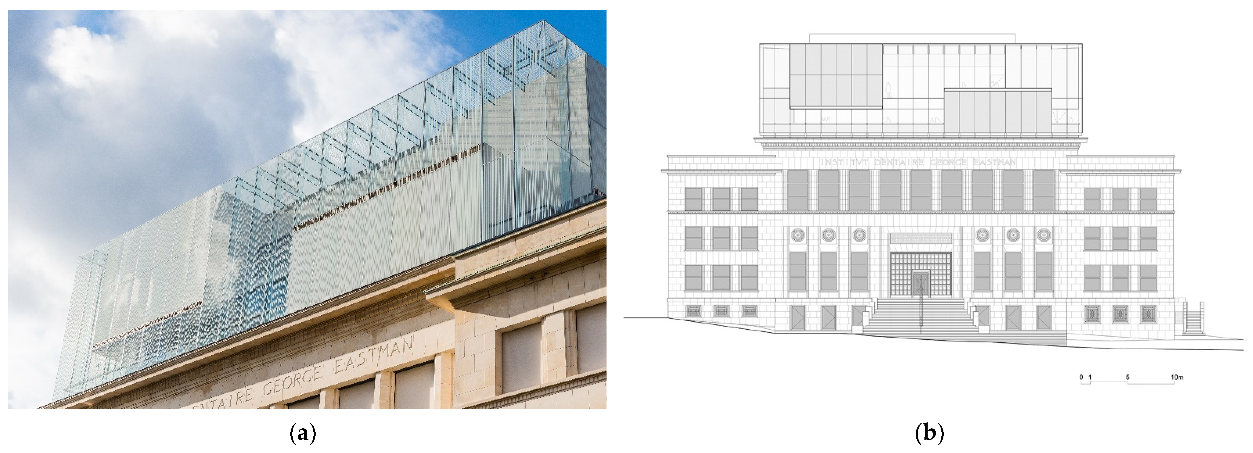
Table 1.
Chronological list of analysed all-glass objects.
| Name of Building | City | Construction Year | Architect/Glass Engineer | The Function of Glass Object | Type of Structural System |
|---|---|---|---|---|---|
| Glass Museum | Kingswinford (GB) | 1994 | Design Antenna/Dewhurst Macfarlane and Partners | Extension—entrance to the museum | frames |
| Footbridge | Rotterdam (NL) | 1994 | Kraaijvanger-Urbis/Rob Nijsee | link between two buildings | glass beams, plate–wall system |
| Kubus Export | Wien (AT) | 2001 | Architects Tillner & Willinger | exhibition pavilion | frames |
| Norwich Castle Lift | Norwich (GB) | 2001 | Purcell | lift | frames |
| Glass Cube Memorial | Mannheim (DE) | 2003 | sculptor Jochen Kitzbihler | sculpture/installation | plate–wall system |
| House at King Henry’s Road | London (GB) | 2003 | Paul Archer Design/Fluid Structures | extension—dining room | beam–wall system |
| Roel Farm Glass Cube | Gloucestershire (GB) | 2004 | Jamieson Associates/Marl Lovell Design Engineers | link between two buildings | grillage system |
| Apple Store Fifth Avenue | New York (USA) | 2006/2011 | Bohlin Cywinski Jackson/Eckersley O’Callaghan | pavilion—entrance to the store | grillage system |
| Rietberg Museum | Zurich (CH) | 2006 | ARE Grazioli, Krischnzitz/Ernst Basler + Partner AG, Ludwig + Weller | pavilion—entrance to museum | frames |
| Apple Store 367 George Street | Sydney (AU) | 2007 | Bohlin Cywinski Jackson/Eckersley O’Callaghan | extension—facade | frames |
| John Lewis Department Store | Leicester (GB) | 2008 | Foreign Office Architects FOA/AKT-II | link—footbridge between two buildings | beam–wall system |
| American Academy of Arts and Letters | New York (USA) | 2009 | JVC Architect/Robert Silman Associates | glass link between two buildings | glass beams, steel frames in walls |
| House at Mapledene Road | London (GB) | 2009 | Platform 5 Architects | extension—kitchen/dining room | plate–wall system |
| Leibniz Institute for Solid State and Material Research pavilion | Dresden (DE) | 2009 | Blum und Schultze Architekten/GSK—Glas Statik Konstruktionen GmbH | exhibition pavilion | frames |
| Apple Store Pudong | Shanghai (CN) | 2010 | Bohlin Cywinski Jackson/Eckersley O’Callaghan | pavilion—entrance to the store | grillage system, glass frames |
| President’s House | Philadelphia (USA) | 2010 | Kelly Maiello Architects/Rydal Engineering | exhibition pavilion | grillage system |
| The Park Hotel | Hyderabad (IN) | 2010 | SOM/SOM | link between buildings | frames |
| Costa Coffee Tower Vaults | London (GB) | 2011 | Dyer/IQ Project | extension—tearoom | frames |
| House at Souldern Road | London (GB) | 2011 | DOS Architects/Firman Glass | extension—living room | frames |
| New Headquarters Bank of Georgia | Tbilisi (GE) | 2011 | Architectural Group and partners (AG&P)/Verroplan GmbH | pavilion—entrance to the office | grillage system |
| 60 Victoria Embankment | London (GB) | 2012 | TP Bennett/OAG | extension—entrance to office | frames |
| Coach Restaurant | Hatfield (GB) | 2012 | Brooks/Murray Architects/ | extension—dining room | frames |
| Glass Cube | Haarlem (NL) | 2012 | Kraaijvanger Architects/ABT–Rob Nijsse | pavilion—entrance to underground car parking | glass fins and steel cables |
| Glass House Milnthorpe Corner | Winchester (GB) | 2012 | AR Design Studio | extension—kitchen/dining room | frames |
| House at Castelnau | London (GB) | 2012 | RRA Architects/Culmax | extension—living room | beam–wall system |
| Westfield Shopping Center | Sydney (AU) | 2012 | John Wardle Architects | link—footbridge between two buildings | frames |
| Castle Grimma | Grimma (DE) | 2013 | Bauconzept/GSK—Glas Statik Konstruktionen GmbH | link between buildings | frames |
| Daman Building | Dubai (UAE) | 2013 | Perkins & Will/Malishev Engineers | Pavilion—entrance | grillage system |
| Dilworth Park | Philadelphia (USA) | 2014 | Kieran Timberlake/Eckersley O’Callaghan | pavilions—entrance to underground station | plate–wall system |
| Salvation Army Conference Center | Sunbury Court (GB) | 2014 | Dyer | extension—dining room | frames |
| Bestseller Building | Aarhus (DK) | 2015 | C. F. Møller/Skandinaviska Glasssystem | Pavilion—entrance | grillage system |
| Bodelwyddan Castle | Bodelwyddan near Rhyl (GB) | 2015 | PWP Architects/O J Taffinder Ltd. | hotel/restaurant entrance | frames |
| Spencer Park House | London (GB) | 2015 | Borgos Pieper/Eckersley O’Callaghan | extension—living/dining room | beam–wall system |
| Centraal Museum | Utrecht (NL) | 2016 | SODA/ABT | link—footbridge between two buildings | plate–wall system |
| Pier Visitor Center | Clevedon (GB) | 2016 | O’LearyGoss Architects/Glass Solution | extension—tea room | frames |
| The Liberty Square/The National Forum of Music | Wroclaw (PL) | 2016 | ASPA Pracownia Projektowa | pavilions—entrance to underground parking | grillage system |
| House of European History | Brussels (BE) | 2017 | Chaix & Morel et Associés; JSWD Architects/Werner Sobek | upper extension | frames, grillage system |
| House Christchurch | London (GB) | 2009/2017 | Mc2design/Markam Associates | extension—living room | beam–wall system |
| Tottenham Court Road Underground Station | London (GB) | 2017 | Stanton Williams/Seele | pavilions—entrance to underground station | glass frames with steel inserts |
| Apple Piazza Liberty | Milan (IT) | 2018 | Foster + Partners/Eckersley O’Callaghan | pavilion—entrance to the store | plate–wall system |
| Burford Lane Farm | Burford (GB) | 2018 | James Bell Architecture | link between two buildings | frames |
| Lahti Travel Center | Lahti (FI) | 2018 | JKMM | pavilion—entrance to underground station | grillage system |
| Restaurant pavilion Wienerwirt | Graz (AT) | 2018 | Claire Braun/Karner Consulting | pavilion—dining pavilion | grillage system |
| Office in Chiswick | London (GB) | 2019 | Paul Vick/Malishev Engineers | link between two buildings | glass frames, plate–wall system |
| Residential at Woodsford Square | London (GB) | 2020 | Shape Architecture | extension—living/dining room | plate–wall system |
| Tourist information point | Glurns (IT) | 2020 | Jürgen Wallnöfer/GBD Group | pavilion—inside building | frames |
| The old vicarage, Ambrose Place | Worthing (GB) | 2021 | Saville Jones Architects/Glass Structures Limited | extension—dining room | frames |
| The Craiova Art Museum | Craiova (RO) | 2022 | Dorin Stefan/GSK | exhibition pavilion | glass wall systems with glass fins |
Table 2.
General physical and mechanical properties of basic soda lime silicate glass [28].
Table 2.
General physical and mechanical properties of basic soda lime silicate glass [28].
| Type of Properties | Value |
|---|---|
| Modulus of elastisity | E = 70,000 MPa |
| Poisson’s ratio | v = 0.23 |
| Coefficient of linear thermal expansion | αt = 9 × 10⁻⁶ L/K |
| Glass density | ρ = 2500 kg/m3 |
Table 3.
Analysis of the geometrical condition of the glass frames.
| Name of Building, City | Types of Glass Frames | Distance between Frames S | Span of the Frame/Rafter L | Height of Column H | Cross-Section of the Rafter hrafter × b | Ratio | Cross-Section of the Column hcolumn × b | Ratio |
|---|---|---|---|---|---|---|---|---|
| [m] | [m] | [m] | [mm] | [mm] | ||||
| Glass Museum, Kingswinford (GB) | half frame | 1.10 | 5.70 | 3.50 | 300 × 33.00 | 200 × 33.00 | ||
| Rietberg Museum, Zürich (CH) | portal frame | 1.80 | 4.40 | 6.48 | 350 × 26.28 | 350 × 42.00 | ||
| Leibniz Institute for Solid State and Material Research, Dresden (DE) | portal frame | 1.90 | 4.40 | 2.77 | 250 × 36.00 | 250 × 36.00 | ||
| Costa Coffee Tower Vaults, ondon (GB) | half frame | 1.50 | 4.50 | 2.70 | 300 × 44.50 | 200 × 44.50 | ||
| Souldern Road House, London (GB) | half frame | 1.00 | 3.10 | 2.40 | 270 × 39.00 | 250 × 39.00 | ||
| Bank JP Morgan, London (GB) | half frame | 2.90 | 7.90 | 7.20 | 700 × 57.10 | 600 × 57.10 | ||
| Castle Grimma, Grimma (DE) | half frame | 1.50 | 2.50 | 2.20 | 300 × 45.30 | 300 × 45.30 | ||
| Pier Visitor Center, Clevedon (GB) | portal frame | 1.50 | 3.94 | 2.19 | 250 × 39.00 | 250 × 39.00 | ||
| House of European History, Brussels (B) | half frame | 1.65 | 1.60 ÷ 5.60 | 3.00 ÷ 14.00 | 350 × 80.00 | 350 × 80.00 |
Table 4.
Relationship between the structural systems and the functional-spatial, the forms, and the function aspects.
Table 4.
Relationship between the structural systems and the functional-spatial, the forms, and the function aspects.
| Functional-Spatial Types of All-Glass Object | Forms | Structures | |||
|---|---|---|---|---|---|
| Frames System | Grillage System | Beam-Wall System | Plate-Wall System | ||
| Pavilions | Cubic | ○ | ●●● | ○ | ● |
| Cuboid | ●●● | ●● | ●● | ● | |
| Cylinder | ○ | ●● | ○ | ○ | |
| Free-form | ●●● | ○ | ○ | ● | |
| Extensions | Cubic | ○ | ○ | ○ | ○ |
| Cuboid | ●●● | ○ | ●● | ●● | |
| Cylinder | - | - | - | - | |
| Free-form | ● | ○ | ● | ○ | |
| Links | Cubic | ○ | ○ | ○ | ○ |
| Cuboid | ●●● | ○ | ●● | ●● | |
| Cylinder | - | - | - | - | |
| Free-form | ○ | ○ | ○ | ○ | |
Publisher’s Note: MDPI stays neutral with regard to jurisdictional claims in published maps and institutional affiliations. |
© 2022 by the author. Licensee MDPI, Basel, Switzerland. This article is an open access article distributed under the terms and conditions of the Creative Commons Attribution (CC BY) license (https://creativecommons.org/licenses/by/4.0/).
Share and Cite
MDPI and ACS Style
Jóźwik, A. Application of Glass Structures in Architectural Shaping of All-Glass Pavilions, Extensions, and Links. Buildings 2022, 12, 1254. https://doi.org/10.3390/buildings12081254
AMA Style
Jóźwik A. Application of Glass Structures in Architectural Shaping of All-Glass Pavilions, Extensions, and Links. Buildings. 2022; 12(8):1254. https://doi.org/10.3390/buildings12081254
Chicago/Turabian StyleJóźwik, Anna. 2022. "Application of Glass Structures in Architectural Shaping of All-Glass Pavilions, Extensions, and Links" Buildings 12, no. 8: 1254. https://doi.org/10.3390/buildings12081254
Note that from the first issue of 2016, this journal uses article numbers instead of page numbers. See further details here.