
Environment-Induced Performance of End Concrete Diaphragm in Skewed Semi-Integral Bridges

1
2LMN, Inc., 1105 Schrock Rd., Ste. 516, Columbus, OH 43229, USA
2
Stocker Center, Department of Civil Engineering, Ohio University, Athens, OH 45701, USA
*
Author to whom correspondence should be addressed.
Buildings 2022, 12(11), 1985; https://doi.org/10.3390/buildings12111985
Submission received: 25 September 2022
/
Revised: 6 November 2022
/
Accepted: 10 November 2022
/
Published: 16 November 2022
(This article belongs to the Special Issue Structural Health Monitoring of Buildings, Bridges and Dams)
Abstract
:Past research has shown that as skewed bridges change temperature, additional lateral movement or forces will occur along with the elongation of the bridge. Even though past research has documented this behavior, lateral movements of semi-integral bridge superstructure associated with temperature effects on bridge skewness have not been well predicted. In this study, the seasonal movements of a 24-year-old semi-integral bridge caused by temperature effects with skewed abutment have been investigated by conducting a series of field measurements on bridges subjected to various environmental climates. The measured data showed that as the bridge heated up, the superstructure tended to move toward the acute corner of the bridge, and the bridge would contract towards its obtuse corner with a negative temperature change. During warm weather, the cracks on the end diaphragm tended to open with a positive temperature change and close with a negative temperature change, which was much more predictable than the cold weather behavior. This behavior confirms that even though the bridge moves linearly with temperature, the end diaphragm response to the temperature depends on the season. Movement of the bridge superstructure from temperature change has caused cracks in the end diaphragm, which are now propagating to the deck. These cracks could damage the bridge enough that it would require repair work in the future. The evidence in this study will help provide a complete picture of seasonal jointless bridge behavior so future semi-integral bridges can be made safer and more efficient.
1. Introduction
In recent years, bridges without expansion joints in the deck have been more desirable because of lower maintenance costs and longer lifespans [1,2,3,4,5]. When an expansion joint is used in a bridge deck, elements such as chemicals and debris can leak through the joints and cause problems such as joint spalling, freezing, and thawing as well as corrosion [6]. However, even with the benefits of using jointless bridge construction, unique problems occur with both semi-integral abutment bridges and fully integral abutment bridges that associates with the bridge skewness [7]. When deciding if a semi-integral or fully integral bridge is more appropriate, it is important to find the type and magnitude of the forces it is subjected to. The semi-integral design provides a more flexible system that allows more unrestricted movement [8]. A fully integral bridge is a more rigid system that depends on the bridge acting as one piece. This means that a fully integrated bridge must be designed to handle larger stress concentrations, while the semi-integral bridge must be designed to handle larger displacements. Design codes specify that semi-integral abutment bridges are required to use when the skew angle of the bridge is above 30-degree angle [1,2,3,9,10,11,12,13].
The end diaphragm connects the girders, so they act together as one piece and provide stiffness to the bridge [2,14]. The girders and deck are the primary items considered during the design phase of the bridge, but this can cause the end diaphragm to be overlooked. It is the purpose of the end diaphragm to transfer the vertical loads from the superstructure via an elastomeric bearing pad to the substructure [1,8]. This bearing pad is typically assumed to only vertical transfer loads, which the abutment and foundation then transfer to the soil. Both concrete and steel girders use an end diaphragm, which can be made from either steel or concrete, but the latter is the more common. There are many unknown variables associated with quantifying the stresses developed from the temperature effects with skewed abutment in relation to the differential heating and cooling of the bridge [6]. Usually, the bridge designer must use their engineering judgment when it comes to handling the effect that skew angle plays on end diaphragms. As it could be easy to overlook additional loadings that are developed from the thermal expansion of a skewed bridge, more attention is necessary to analyze the behavior of bridge end diaphragms.
Precautions should be taken to understand all the side effects of utilizing the semi-integral bridge’s flexible nature when designing the sub-structure of the bridge as well as the superstructure. Standard codes do not provide a prediction of thermal movements in the transverse direction of the skewed semi-integral bridge. It provides and describes the effect of the thermal movements in skewed bridges that may help to improve the design of end diaphragm in a skewed semi-integral bridge to minimize the cracks at the ends of skewed bridges. The objective of this study is to investigate the performance of a 47.5° skewed semi-integral bridge by conducting a series of field measurements on bridges subjected to various environmental climates. This high level of skewness sets this bridge apart from most bridges and amplifies the effects associated with skew and temperature change. The evidence in this study will help provide a complete picture of seasonal jointless bridge behavior so future semi-integral bridges can be made safer and more efficient.
2. Literature Review
It has been established by past research [8,15] that significant forces from temperature effects with skewed abutment will be developed and must be considered into the bridge design. The problem associated with skewness and temperature is that there is no perfect way to quantify how the bridge will react. The bridge behavior can depend on the size and shape along with the general site conditions. According to Burke [8], when the superstructure of a semi-integral bridge is supported by elastomeric pads, it can be assumed that the superstructure and substructure act “almost” independent of each other. The lateral resistance of the superstructure is developed from its interaction with the backfill material. The skewness of a bridge’s geometric shape causes additional forces associated with temperature change to develop. The thermal expansion of the bridge causes it to expand or contract within a space that is confined. This additional movement can cause issues to the design of the overall structure if it has not been accounted for.
There is currently no specific standard for allowable limits of integral abutment bridge components in the United States, according to Tabatabai et al. [16]. Instead, each state has state-specific requirements that must be met. The study by Tabatabaiet al. [16] was performed to consolidate the individual requirements of each U.S. state when designing integral abutment bridges. These requirements found by the authors included maximum girder length, maximum skew angle, and the types of foundations typically used. The highest skew angle permitted was 20 degrees for 4 states, 25 degrees for 2 states, 30 degrees for 14 states, 45 degrees for 6 states, and 11 states did not have a maximum skew angle available.
With more future research relating bridge behavior to the skewness of the bridge, a national specification could be used to standardize the procedure for designing skewed integral abutment bridges Tabatabai [16]. There is no perfect solution or absolute bounds for which a skewed bridge could be used. However, there will be some uncertainty when dealing with skewed bridges because of the variable behavior which has been shown in past research [15,17,18].
To better understand the behavior of semi-integral bridge behavior, the behavior of a fully integral bridge should be looked at as a comparison. LaFave et al. [19] investigated the performance of two fully integral abutment bridges located in Illinois under environmental factors. All of their collected data trended with the ambient temperature change and showed strong tendencies for larger strains to develop in the piles that were on the acute angle corner of the foundation, which is what was predicted would happen. The magnitudes of strain developed in the girders measured by LaFave et al. [19] could be of concern and should be accounted for in future designs, but the relative rotation of the abutment to the superstructure was of a small magnitude and was not a major concern for the integrity of the bridge.
Arsoy [20] studied the behavior of semi-integral bridge abutments subjected to cyclic temperature change to determine if the connection between pile caps and the abutment could transfer loads and moments under cyclic conditions over the expected lifespan of a semi-integral bridge. Understanding issues associated with semi-integral bridges such as the research by Arsoy [20] is just as important as understanding the benefits from using them. The research performed by Hussein et al. [21] helps demonstrate the importance of recognizing the effect that seasonal weather can have on a bridge as well as the combined effect that weather and normal loadings can have on the integrity of the bridge. Similarly, temperature loads on a skewed bridge combined with design loads could affect the bridge in a way it was not designed to handle originally. More care needs to be taken to better quantify the effect that temperature can play on semi-integral bridges. The research provided by this thesis will help give a better framework of knowledge of skewed bridge behavior relating to temperature change.
Bridges that would typically experience large horizontal movements utilize guide bearings to manage the direction and magnitudes of these movements [22]. If bridge superstructure movements are not restricted, and lateral movements are more than expected, the only thing that can stop the lateral movement would be a buttress or wing wall depending on the style of the bridge. This is the reason that several studies, such as report FHWA/VCTIR 12-R10 by Hoppe [18] and the report FHWA/OH-2010/16 by Steinberg and Sargand [23], have investigated the cracking of wing walls due to excessive lateral movement associated with changes in temperature relative to the skewness of a bridge. More research is needed to quantify better the behavior of skewed bridges and how horizontal movements, or forces are transferred to the substructure of the bridge. From the research conducted in this study, skewed semi-integral bridge end diaphragm behavior was better quantified and documented.
The information gathered from this literature review helps demonstrate some of the general behavior and issues associated with skewed bridges. Many studies have been done to better quantify the forces developed in the girder/deck or the sub-structure/wing- wall of bridges [15,17,18,22]; however, there has been no known research into the behavior of skewed bridge end diaphragms. There is uncertainty when designing skewed bridges, which is one reason regulations vary from state to state [16]. There is a similar issue when designing end diaphragms of bridges, with an accepted general layout typically associated with a state regulation. When designing a skewed end diaphragm, it is expected for the designer to use experience or engineering judgement to complete the final design while considering additional forces from temperature effects with skewed abutment. It would be easy not to consider the additional temperature effects when the primary service loads on the bridge dominate the design of the bridge.
The bridge instrumented in this study is located near Logan, Ohio, on State Route 180, which overpasses U.S. Route 33. This bridge was constructed approximately 24 years ago in the summer of 1994. The purpose of instrumenting this bridge in 1994 by Metzger [17] was to measure the forces that developed in the bridge girders, deck and backfill material better to quantify the temperature effects with skewed abutment on the bridge. Metzger [17] found that the forces in the bridge increased as the bridge heated up and decreased as it cooled down, but no numerical correlation was found. Metzger [17] concluded that with the measurements collected from the field, no stresses outside of the allowable limits were found. This statement shows that nothing was initially stressed beyond what was expected and that the bridge appeared satisfactory shortly after construction.
Burke [8] provided several examples of interesting jointless bridges that might help illustrate or highlight deck cracking issues associated with jointless bridges. More specifically, a bridge that is located at the overpass of US-33 and SR 180, which is the same bridge being analyzed for this research. During the construction of this bridge, the longitudinal expansion joints on the acute corners of the bridge compressed to half their thickness. It was also noticed that the joints at the obtuse corners were falling away from the abutment because of the gap formed between the abutment and end diaphragm. This initial movement of the bridge superstructure illustrates the issue that temperature can play when dealing with highly skewed bridges. This initial movement also shows that either something was not properly accounted for with the design, or something was not properly installed with this bridge. Interestingly, if this bridge movement is considered along with data from Metzger [17], it could be hypothesized that even with the excessive bridge movements, no damaging stresses developed within the bridge initially.
3. Experimental Program
3.1. Apparatus
In this research, the field monitoring method was used to identify the effect of the environmental factors on 47.5° skewed semi-integral under various climates. This high level of skewness sets this bridge apart from most bridges and amplifies the effects associated with skew and temperature change. The field monitoring method was used in an attempt to measure the movements in longitudinal and transverse directions of the end diaphragm along with cracks opening and closing. In order to study the behavior of the bridge as it heats and cools with changes of ambient air temperature, the forward abutment was instrumented. To measure the movements of the bridge superstructure, thermocouple gauges, displacement gauges, and strain gauges were installed. The strain gauges were installed across the vertical cracks, which were located along with the end diaphragm beside each girder along with temperature in order to measure opening and closing across the cracks of the end diaphragm as the bridge heats and cools. The displacement gauges were placed at the interface between the sides of the wing walls and the sides of the end diaphragm to measure the relative displacement between them. The displacement of the end diaphragm is not the absolute movement of the superstructure, but rather the measured relative displacement between the superstructure and substructure of the bridge. Thermocouple gauges were used to measure the temperature of the steel girders and in the concrete deck of the bridge. These temperature readings helped to show the relation between the maximum or minimum temperatures to the maximum or minimum movements of the bridge superstructure. Additionally, the temperature sensors were used to measure the temperature behind the abutment in the backfill material. These temperature measurements helped to demonstrate how ambient air temperature change affects the temperature of the entire bridge structure.
3.2. Bridge Description
The bridge instrumented in this study is located near Logan, Ohio, on State Route 180, which overpasses U.S. Route 33, as shown in Figure 1. The bridge is a two-span semi-integral bridge with a concrete pier at the mid-span and was constructed during the summer of 1994. Each span is 116 feet long with five steel plate girders, which are shear connected to its concrete deck. The bridge is skewed 47.5 degrees with integral approach slabs, and a bridge deck width of 47 feet. The five steel girders were integrally cast into a concrete end diaphragm, which sits on elastomeric bearing pads. These bearing pads allow the superstructure of the bridge to move laterally while transferring the vertical loads. Styrofoam was placed in the gap between the end diaphragm and the bridge abutment and neoprene sheeting was used to prevent water from flowing through the soil and into this gap. The wing walls of this bridge were integrally cast into the abutment. Expansion joints with2-inch gaps were placed between the side of the end diaphragm and wing wall to allow horizontal movement. This expansion joint was expected to allow the bridge to expand and contract with the temperature change in the transverse direction.
3.3. Instrumentation and Data Collection
The forward abutment located near the westbound lane of U.S. 33 has been instrumented to study the behavior of the bridge as it heats and cools with changes of ambient air temperature. To measure the movements of the bridge superstructure, thermocouples, linear variable displacement transformers (LVDTs), and vibrating wire strain (VW) gauges were installed. Only the forward side of the bridge was instrumented to conserve the number of instruments needed and the symmetric nature of the bridge.
The VW strain gauges were installed across the vertical cracks, which were located along with the end diaphragm beside each girder. These cracks developed at the centerline of the bridge girder bearing pads and projected out perpendicular to the face of the end diaphragm. To measure the relative opening and closing across the concrete cracks at these locations, brackets were fixed to the bridge end diaphragm. With the proper brackets installed, strain gauges were secured into place with set screws to measure the relative opening and closing of the cracks. Figure 2 shows a strain gauge after it was installed near girder #4. The VW strain gauges can measure both temperature and strain, which will both be used to measure opening and closing across the cracks of the end diaphragm as the bridge heats and cools. These strain gauges were numbered and placed across the cracks of each corresponding girder. Figure 2 shows the locations of each VW strain gauge. The VW strain gauges have a resolution of plus or minus 0.1 micro-strain within the gauge’s range of measurement. The relative displacement of the strain gauge ends, measured as strain, are used to quantify the movement across the discontinuity (cracks) on the face of the end diaphragms.
The LVDTs were placed at the interface between the sides of the wing walls and the sides of the end diaphragm to measure the relative displacement between them. The displacement of the end diaphragm is not the absolute movement of the superstructure, but rather the measured relative displacement between the superstructure and substructure of the bridge. LVDTs (#1, #3, #4, and #6) were placed near the top and bottom of the end diaphragm on both sides of the foreword abutment to measure the longitudinal displacement of the bridge superstructure. To measure the transverse movement of the bridge superstructure, LVDTs (#2 and #5) were placed on both ends of the end diaphragm parallel with the face of the bridge abutment. Figure 2 shows the locations of the LVDTs on the foreword abutment of the bridge. Figure 3 shows LVDTs #1, #2, and #3, located on the obtuse corner of the foreword abutment.
Thermocouple gauges were used to measure the temperature of the steel girders and in the concrete deck of the bridge. Additionally, a single thermocouple was placed in the open air near the acute corner of the forward abutment to measure the ambient air temperature around the bridge. Thermocouples were also placed in the surface of the deck and at the mid depth of the deck to see the temperature gradient across the bridge deck. Additionally, three thermocouple gauges were installed in the top flange, mid web and bottom flange of the #1, #3, and #5 girders to obtain the temperature gradient across the bridge girders. These temperature readings helped to show the relation between the maximum or minimum temperatures to the maximum or minimum movements of the bridge superstructure. Additionally, the temperature sensors were used to measure the temperature behind the abutment in the backfill material. These temperature measurements helped to demonstrate how ambient air temperature change affects the temperature of the entire bridge structure. A data logger was used to collect the hourly data through periods of desired temperature changes from the LVDTs, the VW strain gauges, and the thermocouples.
4. Results
4.1. Propagation of Cracks in the Bridge End Diaphragms
Each end diaphragm had a length of 76′–8½″ a width of 3′–9″ and a maximum depth of 6′–8″ at the outermost points. This large piece of concrete encased the ends of the five steel plate girders so that the bridge superstructure behaved as one piece. After the bridge was constructed in 1994, cracks developed in the end diaphragms at the bearing pads, which projected perpendicularly to the end diaphragm surface. Figure 4 shows the vertical cracks in the end, diaphragm located at the projected centerline of the girder bearing pad.
The number and length of each crack vary, but each crack starts at the bottom of the diaphragm and propagates towards the bridge deck. In some locations, these cracks reached the bridge deck, which is shown in Figure 4. The progressive cracking along the end diaphragm could potentially damage the deck enough that it would need to be replaced in the future. The surface of the bridge deck appeared to be an inadequate condition with no major cracking noticed. It should be noted that the bridge deck was resurfaced in 2012 with no issues related to replacement of the deck surface, as reported by ODOT [24,25]. To prevent future issues associated with the deck, the cracks on the bottom of the deck should be monitored.
4.2. Movement of Bridge Superstructure
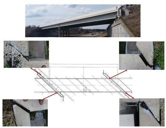
The initial inspection of the bridge shows that the bridge superstructure has displaced significantly since it was initially constructed. Figure 5 shows the current condition of the expansion joint between the end diaphragm and the wing walls. The expansion joints between the wing walls and end diaphragm were originally 2 inches thick, but after excessive lateral movement, they have deformed over time. Table 1 shows how much each expansion joint has been opening and closing.
As the bridge superstructure is heating up and expanding, it tends to rotate away from its abutments, which it is supported. The opening of the obtuse corner expansion joints and the compression of the acute corners of the bridge shown in Table 1 illustrates this finding. The relative displacements of these expansion joints do not appear to be recoverable. As the bridge heats and cools, these joints move cyclically back in forth in small increments. However, it appears that the large displacements of over half their thickness will not be reversed but will continue to be deformed over time. It is debatable if this deformation has reached a state of equilibrium or if the bridge superstructure will progressively move laterally.
4.3. Secondary Issues
The primary problems occurring at this bridge have been caused by the horizontal rotation of the bridge driven by the temperature effects with skewed abutment. This rotation of the bridge superstructure has been causing problems for parts of the bridge other than the girders, deck, or end diaphragm. The approach slabs of this bridge are integrally reinforced with the bridge deck and end diaphragm so that the approach slab acts concurrently with the superstructure. It is for this reason that when the bridge superstructure rotates from the temperature effects with skewed abutment, the approach slab must also rotate. This rotation of the approach slab caused it to dip vertically overtime at the asphalt/concrete interface, and for the curbs at the sides of the slab to be displaced horizontally. This behavior can be seen in Figure 6. For this reason, asphalt pavement was placed by maintenance crews on top of the beginning of the approach slab. The added asphalt provides a continuous elevation for vehicles to travel across, but it does not fix the issue of the approach slab movement. Currently, the approach slab condition is not a structural problem, but it should be monitored in the future to ensure that it does not turn into a problem.
The bridge wing walls are integrally attached to the abutment and act independently of the superstructure and end diaphragm. When the bridge superstructure displaces laterally, the soil interaction on the bridge and the wing wall will be the only parts that will resist the movement. For this reason, it is typical to see the cracking of wing walls of skewed bridges. Significant research has been conducted on the cracking of wing walls of skewed bridges such as the research done by LeFave [19], Shehu [22], and Steinberg [23]. When considering the high skew angle of 47.5° for the bridge being researched, it would be expected to see the cracking of wing walls. However, the wing wall is not what is starting to crack, but rather the end diaphragm. The compression of the expansion joints hypothetically protects the wing walls from developing excessive forces on them. This means the wing wall was properly designed, and it is interesting to note the good condition of the wing walls even with the high bridge skew angle due to the use of straight wing wall compared to turn wing wall.
4.4. Temperature Measurements
In order to compare the results measured with the LVDTs and strain gauges, the temperature change of the bridge site overtime was required. Thermocouples were placed in the deck, and a thermocouple was used to measure the ambient air temperature around the bridge. The thermocouples and the temperature component were used to quantify the temperature gradient across the site better. Figure 7 shows the distribution of temperatures measured during a period of warm weather along with AASHTO [26] temperature limitations.
4.5. LVDT Displacement Measurements
After the bridge was initially constructed, it was subjected to many changes such as initial settlement, creep, shrinkage, and compaction of fill material. By instrumenting the bridge 24 years after it was constructed, the initial erratic movements will have stopped, and the bridge movement will be more uniform. This means the measured bridge movements occurred when the superstructure was at a point of equilibrium. The bridge end diaphragm is a critical location of a semi-integral bridge where longitudinal and vertical forces are transferred, and significant horizontal movements can occur. By instrumenting the bridge end diaphragm, a better understanding of the highly skewed bridge behavior as it undergoes temperature changes can be understood.
In order to measure the daily temperature-induced movements of the bridge end diaphragm, LVDTs were placed between the wing walls and end diaphragm. This relative displacement demonstrates how the bridge superstructure is affected by both daily heating and cooling as well as the seasonal heating and cooling. During periods of rapid changes in temperature, the bridge displacements are prone to behave more erratically. To better demonstrate the general behavior of the bridge, Figure 8 shows the typical lateral and longitudinal displacement trends of the bridge on a warm day.
The reason LVDT #2 and #5 have opposite directions is because the LVDTs are oriented in opposite directions. LVDT #2 and #5 are measuring the lateral relative displacements between the end diaphragm and the wing walls on the obtuse and acute corners, respectively, of the forward side of the bridge. When LVDT #5 moves positively and LVDT #2 moves negatively, this means the bridge superstructure is moving towards the acute corner. Figure 8 shows that as the bridge heats up in warm weather, the end diaphragm moves towards the acute corner of the bridge, as shown by the displacement of LVDT #2 and LVDT #5, which mirror the movements of the other in the same direction. However, it can also be noted that there is a slightly more lateral movement noticed at the acute corner of the bridge (LVDT #5) than the obtuse corner of the bridge (LVDT #2).
Figure 9 shows the longitudinal movement of the end diaphragm as it heats and cools during typical warm weather. As the temperature increases, LVDT #3 and LVDT #6 show more longitudinal movement at the bottom of the end diaphragm than the top portion with LVDT #1 and LVDT #4. This is caused by the steel girders heating and cooling quicker than the concrete deck does. The more longitudinal movement was also noticed on LVDT #4 and LVDT #6 because this side of the bridge would have direct sunlight as the sun started to rise. Figure 9 shows the longitudinal expansion of the bridge superstructure on a typical period of cold weather.
The data in Figure 10 confirms this behavior because the movements are symmetric and decrease with the positive temperature change. The movements of the bridge end diaphragm appear to trend linearly with temperature, which is shown in Figure 10. The comparison of temperature and displacement of each LVDT is shown in Figure 11 along with the linear fit between temperature and displacement. The linear fit of the LVDTs had an average R2 value of 0.8, which demonstrates the consistency of the movement relative to temperature. Figure 12 also confirms the linear behavior noticed because each LVDT returns to zero at the same installation temperature they were zeroed.
4.6. Vibrating Wire Strain Measurements
The purpose of the installed strain gauges was to measure the opening or closing of the cracks located along with the end diaphragm. This helps demonstrate the general behavior of this piece of the superstructure during hot or cold weather. The measurement from each gauge gives an indication of how much the cracks at each girder location are moving but will not represent the actual strain in the end diaphragm concrete. The strain gauges did not measure the strain in the concrete, but rather indicate the opening and closing movements of the cracks. When a strain gauge has a positive measurement, the crack is opening, and when the strain gauge has a negative measurement, the crack is closing.
The opening or closing of these cracks depends on the temperature of the structure of the bridge as well as the ambient air temperature. As seen in Figure 13, during typical warm weather as the air temperature increases the cracks along the end diaphragm tend to open and as the temperature decreases the cracks tend to close. It should be noted from Figure 13 that the acute side of the bridge (VW#4) tends to open more than the other cracks with a positive temperature change, and the obtuse side cracks (VW#1) of the bridge tend to close more than the other cracks with a negative temperature change. The cracks located in the middle of the end diaphragm tend to behave similarly with lower magnitudes than the cracks found closer to the ends of the end diaphragm. When the cold weather behavior is compared with the warm weather behavior, it is easy to see that both daily temperature change and time of year affect how the bridge will react. Figure 13 shows the end diaphragm behavior during a week period of cold weather.
Figure 13 shows that under cold weather conditions, as the temperature increases or decreases, the response of the gauges is not always the same. The behavior of the diaphragm during the winter season shown in Figure 13 does not match the warm weather behavior also shown in Figure 13. This illustrates how the end diaphragm behavior depends on the ambient temperature and the time of year. It is hypothesized that this erratic crack movement is caused by the overall seasonal contraction of the bridge as it cools down. This causes the end diaphragm to pull away from the backfill material, which changes the superstructure’s response to temperature change. This change in behavior also appears when the soil and air temperature fluctuate around the freezing point. This would allow freezing and thawing in the end diaphragm cracks, and backfill material, which could also change the response of the bridge end diaphragms. Figure 14 compares the end diaphragm behavior through seasonal temperature changes and shows how the cracks start to close as the seasonal temperature drops.
5. Discussion
To understand the skewed bridge behavior caused by temperature change, displacement, strain, and temperature data were analyzed together. It is essential to look at the trends in data at maximum and minimum temperatures, as well as general trends as the bridge is heating up or cooling down. The propagation of cracks in the bridge end diaphragms could potentially damage the deck enough that it would need to be replaced in the future. The surface of the bridge deck appeared to be an inadequate condition with no major cracking noticed. It should be noted that the bridge deck was resurfaced in 2012 with no issues related to replacement of the deck surface, as reported by ODOT [24,25]. To prevent future issues associated with the deck, the cracks on the bottom of the deck should be monitored.
For movement of bridge superstructure, the initial inspection of the bridge shows that the bridge superstructure has displaced significantly since it was initially constructed. The expansion joints located between the wing-walls and the end diaphragm have started to deteriorate from seasonal bridge movement and weathering. As the bridge superstructure has been moving over time, the expansion joints located at the acute corners have started to be over-compressed while the expansion joints located at the obtuse corners have been falling away from the bridge. This opening and closing of expansion joints can visually show how the bridge is moving and demonstrates the relative displacements between the bridge wing walls and end diaphragm. The widths of the expansion joints were originally 2-inch-thick pre-molded expansion joint filler (as shown in the plans) before they were deformed over time. The acute corner expansion joints were compressed 1.78 inches for the rearward side of the bridge and 1.29 inches for the forward side of the bridge. While the obtuse corner expansion joints opened 1.28 inches for the rearward side of the bridge and 1.81 inches for the forward side of the bridge.
In order to understand the overall performance of the end diaphragm, temperature and displacement measurements were discussed here. From Figure 7, the deck temperatures reached higher values than the ambient air temperatures reached. This occurs because of the additional heat from thermal radiation, which the girders are mostly protected from. The behavior of the bridge depends on the temperature of the soil and structure as much as the air temperature. The temperature of the soil was used as a baseline to understand what kind of temperatures the bridge structure is dealing with relative to the air temperature measured. The air temperature data collected from Highland Park Weather Station [27] near Logan, Ohio and is shown in Figure 7. This temperature data from a local weather station helps to support and confirm the temperature measurements that were collected.
The bridge end diaphragm is a critical location of a semi-integral bridge where longitudinal and vertical forces are transferred, and significant horizontal movements can occur. By instrumenting the bridge end diaphragm, a better understanding of the highly skewed bridge behavior as it undergoes temperature changes can be understood. Even though the movement is not as significant as the warm weather movement, the LVDTs located at the bottom of the end diaphragm underwent more movement. This supports the idea that the steel girders are expanding and contracting more quickly than the concrete deck, which also has resistance from the approach slab. The lateral displacement of the bridge is caused by the expansion and contraction of the superstructure while it is confined at each end. When the bridge heats up, the data shows that it will move towards the acute corner. However, when the bridge contracts from a negative temperature change, it tends to move towards the obtuse corner of the bridge.
The data in Figure 10, Figure 11 and Figure 12 confirms this behavior because the movements are symmetric and decrease with the positive temperature change. The movements of the bridge end diaphragm appear to trend linearly with temperature. The linear fit of the LVDTs had an average R2 value of 0.8, which demonstrates the consistency of the movement relative to temperature. The linear behavior noticed because each LVDT returns to zero at the same installation temperature they were zeroed. The displacements measured on the acute side of the end diaphragm (LVDT #4, #5, #6) appeared to be slightly larger than those measured on the obtuse side of the bridge (LVDT #1, #2, #3). The average movement of the bridge as the temperature varies from its initial installation temperature. However, when the temperatures started to drop, the bridge started to contract and move more. This helps to show how movement in the warmer months varies from that which is seen in, the colder months.
From strain measurements, it appears that the cracks near the girders closest to the acute corner (VW #4) contract the least, and the cracks near the girders closest to the obtuse corner (VW #1) contract the most. When the relative opening and closing of the cracks during the winter is compared with magnitudes of the summer, the end diaphragm cracks have been contracting as the temperature has decreased. The end diaphragm is contracting as the seasonal temperature drops, but the thermal response of the cracks changes as the season changes. It is thus shown from the data collected that the behavior of the bridge is influenced by the change in temperature of the structure as well as the overall ambient temperature. Although the movement of the bridge superstructure is linear, the bridge behaved differently for the same change in temperature, depending on the season.
6. Summary and Conclusions
Past research has shown that as skewed bridges heat up, additional lateral movement or forces develop. However, past research has also shown that when dealing with jointless bridges quantifying this behavior can be difficult. Data was collected to better document the superstructure and end diaphragm behavior as well as demonstrate the differences in cold or warm weather behavior.
The initial site conditions at the bridge showed that it had undergone some changes since its construction in 1994. The superstructure of the bridge cyclically moved from temperature effects with skewed abutment as the bridge heated and cooled through each season. This is why the expansion joints located between the wing walls and the end diaphragm became deformed over time. This relative movement also caused the approach slab to dip over time from cyclic temperature changes. Cracks also formed along the end diaphragms of the bridge, and these cracks started to propagate to the bridge deck.
From the measured LVDT data, it was noticed that as the bridge heated up, the superstructure tended to move toward the acute corner of the bridge, and the bridge would contract towards its obtuse corner with a negative temperature change. During typical warm weather, the most significant relative lateral movements and displacements were noticed. However, during cold weather, there was not as much lateral movement, but it rather contracted towards the obtuse corner of the bridge as the seasons cooled down.
The cracks on the end diaphragm were located at the centerline of the girder bearing pads. The strain gauges placed over these cracks were used to monitor how the cracks opened or closed as the temperature changed. It was found from collected data that as the bridge cooled down seasonally, the cracks tended to close on average but behaved erratically during winter months. During warm weather, the cracks tended to open with a positive temperature change and close with a negative temperature change, which was much more predictable than the cold weather behavior. This behavior confirms that even though the bridge moves linearly with temperature, the end diaphragm response to the temperature depends on the season.
Movement of the bridge superstructure from temperature change has caused cracks in the end diaphragm, which are now propagating to the deck. These cracks could damage the bridge deck enough that it would require repair work in the future. The bridge movement and behavior depend on the change of temperature as well as the seasonal ambient temperature.
In the future, skew effects driven by the overall change in temperature should be considered into the design of skewed semi-integral end diaphragms. More versatile finite element software could be used to model the semi-integral bridge connection and discontinuities in the end diaphragm. With a more accurate model, skewed bridge behavior could be predicted, so a more effective design can be made. Investigation of the benefits that end diaphragm guides provide when subjected to skewed temperature effects. The cracks in the bottom of the bridge deck should be monitored in case they continue to propagate and compromise the bridge deck.
Author Contributions
Data curation, H.H.H.; formal analysis, H.H.H., I.K. and J.S.L.; investigation, I.K.; methodology, I.K. and J.S.L. and H.H.H.; project administration, I.K.; resources, I.K.; supervision, H.H.H.; writing—original draft, I.K. and J.S.L.; writing—review and editing, H.H.H. and I.K. All authors have read and agreed to the published version of the manuscript.
Funding
This research received no external funding.
Data Availability Statement
Not applicable.
Conflicts of Interest
The authors declare no conflict of interest.
References
- Fu, G.; Dimaria, J.; Zhuang, Y.; Feng, J. Bridge Deck Corner Cracking on Skewed Structures; Department of Transportation, Construction and Technology Division: Lansing, MI, USA, 2007; p. 153.
- Bou Diab, F.; Mabsout, M.; Tarhini, K. Influence of Skew Angle on Live Load Moments in Steel Girder Bridges. Bridge Struct. 2011, 7, 151–163. [Google Scholar] [CrossRef]
- Ebeido, T.; Kennedy, J.B. Girder Moments in Continuous Skew Composite Bridges. J. Bridge Eng. 1996, 1, 37–45. [Google Scholar] [CrossRef]
- Nutt, R.V.; Schamber, R.A.; Zokaie, T. Distribution of Wheel Loads on Highway Bridges; Project Report 12-26; National Cooperative Highway Research Program (NCHRP): Washington, DC, USA, 1988. [Google Scholar]
- Ebeido, T.; Kennedy, J.B. Shear Distribution in Simply Supported Skew Composite Bridges. Can. J. Civ. Eng. 1995, 22, 1143–1154. [Google Scholar] [CrossRef]
- Stringer, D.J.; Burgueño, R. Identification of Causes and Solution Strategies for Deck Cracking in Jointless Bridges; Report RC-1571; Department of Civil and Environmental Engineering, Michigan State University: East Lansing, MI, USA, 2012. [Google Scholar]
- Okumus, P.; Michael, G. Oliva, Mauricio Diaz Arancibia Design and Performance of Highly Skewed Deck Girder Bridges; Report, Project No 0092-16-05; Wisconsin Department of Transportation Research & Library Unit: Madison, WI, USA, 2019.
- Burke, M.P., Jr. Integral and Semi-Integral Bridges; John Wiley & Sons: Hoboken, NJ, USA, 2009. [Google Scholar]
- Ebeido, T.; Kennedy, J.B. Shear and Reaction Distributions in Continuous Skew Composite Bridges. J. Bridge Eng. 1996, 1, 155–165. [Google Scholar] [CrossRef]
- Modjeski and Masters Inc. Shear in Skewed Multi-Beam Bridges; Project Report 20-7/Task 107; National Cooperative Highway Research Program (NCHRP): Washington, DC, USA, 2002. [Google Scholar]
- Huang, H.; Shenton, W.H.; Chajes, J.M. Load Distribution for a Highly Skewed Bridge: Testing and Analysis. J. Bridge Eng. 2004, 9, 558–562. [Google Scholar] [CrossRef]
- Keogh Damien, L.; O’Brien Eugene, J. Bridge Deck Analysis; Taylor & Francis Group: New York, NY, USA, 2005. [Google Scholar]
- Coletti, D.; Chavel, B.; Gatti, W. The Problems of Skew. In Proceedings of the 2005 World Steel Bridge Symposium, Kobe, Japan, 13–16 January 2005. [Google Scholar]
- Beckmann, F.; Medlock, R.D. Skewed Bridges and Girder Movements Due to Rotations and Differential Deflections. In Proceedings of the 2005 World Steel Bridge Symposium, Kobe, Japan, 13–16 January 2005. [Google Scholar]
- Bettinger, C.L. Effects of Thermal Expansion on a Skewed Semi-Integral Bridge. Master’s Thesis, Ohio University, Athens, OH, USA, 2001. [Google Scholar]
- Tabatabai, H.; Magbool, H.; Bahumdain, A.; Fu, C. Criteria and Practices of Various States for the Design of Jointless and Integral Abutment Bridges. In Proceedings of the Third International Workshop on Jointless Bridges, Seattle, WA, USA, 1 June 2017. [Google Scholar]
- Metzger, A.T. Measurement of the Abutment Forces of a Skewed Semi-Integral Bridge as a Result of Ambient Temperature Change. Master’s Thesis, Ohio University, Athens, OH, USA, 1995. [Google Scholar]
- Hoppe, E.J.; Eichenthal, S.L. Thermal Response of a Highly Skewed Integral Bridge; No. FHWA/VCTIR 12-R10; Virginia Center for Transportation Innovation and Research: Charlottesville, VA, USA, 2012. [Google Scholar]
- LaFave, J.; Fahnestock, L.; Brambila, G.; Riddle, J.; Jarrett, M.; Svatora, J.; An, H. Integral Abutment Bridges under Thermal Loading: Field Monitoring and Analysis; Illinois Center for Transportation/Illinois Department of Transportation: Rantoul, IL, USA, 2017. [Google Scholar]
- Arsoy, S.; Duncan, J.M.; Barker, R.M. Behavior of a semi-integral bridge abutment under static and temperature-induced cyclic loading. J. Bridge Eng. 2004, 9, 193–199. [Google Scholar] [CrossRef]
- Hussein, H.H.; Sargand, S.M.; Khoury, I.; Al-Jhayyish, A.K. Environment-Induced Behavior of Transverse Tie Bars in Adjacent Prestressed Box-Girder Bridges with Partial Depth Shear Keys. J. Perform. Constr. Facil. 2017, 31, 04017074. [Google Scholar] [CrossRef]
- Shehu, J. Evaluation of the Foundation and Wingwalls of Skewed Semi-Integral Bridges with Wall Abutments. Master’s Thesis, Ohio University, Athens, OH, USA, 2009. [Google Scholar]
- Steinberg, E.P.; Sargand, S.M.; Bettinger, C. Forces in Wingwalls from Thermal Expansion of Skewed Semi-Integral Bridges; No. FHWA/OH-2010/16; Ohio Department of Transportation, Research & Development: East Liberty, OH, USA, 2010.
- ODOT. Bridge Design Manual; Ohio Department of Transportation (ODOT): Columbus, OH, USA, 2007.
- Ohio Department of Transportation. 7 July 2014. Available online: https://www.dot.state.oh.us/Divisions/Engineering/Structures/standard/Bridges/StandardDrawings/SICD-1-96.pdf (accessed on 7 May 2018).
- AASHTO. LRFD Bridge Design Specifications, 5th ed.; AASHTO: Washington, DC, USA, 2010. [Google Scholar]
- Weather History for KLHQ-August. 2017. Available online: https://www.wunderground.com/history/airport/KLHQ/2017/8/1/CustomHistory.html?dayend=30&monthend=4&yearend=2018&req_city=&req_state=&req_statename=&reqdb.zip=&reqdb.magic=&reqdb.wmo= (accessed on 30 April 2018).
Figure 1.
Bridge details (a) bridge overview, (b) plan view, (c) abutment cross section, and (d) elevation view.
Figure 1.
Bridge details (a) bridge overview, (b) plan view, (c) abutment cross section, and (d) elevation view.

Figure 2.
Instrumentation Layout and Strain Gauges Located at Girders.

Figure 3.
Instrumentation Layout and LVDTs Located at Wingwall.

Figure 4.
Typical cracks at each girder (a) vibrating wire strain gauge located near girder #2, (b) cracks forming in diaphragm (c) cracks forming in bridge deck.
Figure 4.
Typical cracks at each girder (a) vibrating wire strain gauge located near girder #2, (b) cracks forming in diaphragm (c) cracks forming in bridge deck.

Figure 5.
Wingwall joint opining: (a) overview; (b) forward obtuse corner of bridge; (c) forward acute corner of bridge; (d) rearward acute corner of bridge; and (e) rearward obtuse corner of bridge.
Figure 5.
Wingwall joint opining: (a) overview; (b) forward obtuse corner of bridge; (c) forward acute corner of bridge; (d) rearward acute corner of bridge; and (e) rearward obtuse corner of bridge.

Figure 6.
Approach slab deformation (a) pavement cracks at end of approach slab and (b) bridge curb displacements.
Figure 6.
Approach slab deformation (a) pavement cracks at end of approach slab and (b) bridge curb displacements.

Figure 7.
Measured temperatures (a) warm weather temperature variation (b) daily temperature data.

Figure 8.
Measured temperatures and displacements (a) warm weather lateral displacement (b) warm weather longitudinal displacement.
Figure 8.
Measured temperatures and displacements (a) warm weather lateral displacement (b) warm weather longitudinal displacement.

Figure 9.
Measured temperatures and displacements (a) cold weather longitudinal displacement (b) cold weather lateral displacement.
Figure 9.
Measured temperatures and displacements (a) cold weather longitudinal displacement (b) cold weather lateral displacement.

Figure 10.
Average LVDT Displacement vs. Temperature.

Figure 11.
LVDT Monthly Ave. Relative to Temperature.

Figure 12.
Measured temperatures and displacements (a) LVDT #1, (b) LVDT #2, (c) LVDT #3, (d) LVDT #4, (e) LVDT #5, and (f) LVDT #6.
Figure 12.
Measured temperatures and displacements (a) LVDT #1, (b) LVDT #2, (c) LVDT #3, (d) LVDT #4, (e) LVDT #5, and (f) LVDT #6.


Figure 13.
Measured temperatures and displacements (a) warm weather strain gauge movements (b) cold weather strain gauge movement.
Figure 13.
Measured temperatures and displacements (a) warm weather strain gauge movements (b) cold weather strain gauge movement.

Figure 14.
Strain Gauge Monthly Ave. Relative to Temperature.


Table 1.
End Diaphragm Displacements 26 February 2018.
| Side of Bridge | Corner Location | Original Expansion Joint Size (in) | Measured Expansion Joint Size (in) | Change in Expansion Joint Width (in) |
|---|---|---|---|---|
| Forward | Acute | 2 | 0.71 | −1.29 |
| Rearward | Acute | 2 | 0.22 | −1.78 |
| Forward | Obtuse | 2 | 3.81 | 1.81 |
| Rearward | Obtuse | 2 | 3.28 | 1.28 |
Publisher’s Note: MDPI stays neutral with regard to jurisdictional claims in published maps and institutional affiliations. |
© 2022 by the authors. Licensee MDPI, Basel, Switzerland. This article is an open access article distributed under the terms and conditions of the Creative Commons Attribution (CC BY) license (https://creativecommons.org/licenses/by/4.0/).
Share and Cite
MDPI and ACS Style
Hussein, H.H.; Khoury, I.; Lucas, J.S. Environment-Induced Performance of End Concrete Diaphragm in Skewed Semi-Integral Bridges. Buildings 2022, 12, 1985. https://doi.org/10.3390/buildings12111985
AMA Style
Hussein HH, Khoury I, Lucas JS. Environment-Induced Performance of End Concrete Diaphragm in Skewed Semi-Integral Bridges. Buildings. 2022; 12(11):1985. https://doi.org/10.3390/buildings12111985
Chicago/Turabian StyleHussein, Husam H., Issam Khoury, and Joshua S. Lucas. 2022. "Environment-Induced Performance of End Concrete Diaphragm in Skewed Semi-Integral Bridges" Buildings 12, no. 11: 1985. https://doi.org/10.3390/buildings12111985
Note that from the first issue of 2016, this journal uses article numbers instead of page numbers. See further details here.