
Dynamic Modeling and Motion Control Strategy of Cable-Driven Cleaning Robot for Ship Cargo Hold

1
Marine Engineering College, Dalian Maritime University, Dalian 116026, China
2
National Center for International Research of Subsea Engineering Technology and Equipment, Dalian Maritime University, Dalian 116026, China
*
Author to whom correspondence should be addressed.
J. Mar. Sci. Eng. 2023, 11(1), 87; https://doi.org/10.3390/jmse11010087
Submission received: 25 November 2022
/
Revised: 15 December 2022
/
Accepted: 17 December 2022
/
Published: 3 January 2023
(This article belongs to the Section Ocean Engineering)
Abstract
:Ship cargo-hold cleaning is a low-efficiency and high-risk operation in marine industry, which is generally carried out manually, putting the workers in danger. To improve the efficiency and safety of ship cargo-hold cleaning, a C-DCR is proposed in this article. Most research on the dynamics and control of CDPRs has focused on the scenarios with fixed bases; however, the effect of moving-base excitation on the end-effector is largely ignored. In this article, the dynamic model is established based on Lagrange method considering the ship motion and external disturbance, in which the motor model is considered. On this basis, for the high-speed maneuverability of the C-DCR, a modified PD feedforward tracking controller was proposed. Furthermore, the stability of the controller was proved with the Lyapunov Stability Theory. To keep the cable in tension at all times, the tensions are optimized based on the minimum 2-norm method. The simulation results show that the error mean of position is 0.22 m and the angular error mean is 2.8° under ship motion and external disturbance, indicating that the C-DCR has stable, smooth and bounded tracking performance, which will ensure the accuracy of the cleaning operation.
1. Introduction
After the cargo ship has discharged its cargo in port, some non-packaged forms of cargo usually leave a lot of residues on the inside of the cargo hold [1]. The general solution is a manual cleaning operation by workers with water guns or brooms, and a few use wall-climbing robots to complete the cleaning operation [2]. However, the surface of the cargo hold is very large, which limits the scope of manual cleaning and causes some dead zones that cannot be cleaned. The limited ability of wall-climbing robots to cross barriers reduces the range of applications [3,4]. In addition, under the influence of ship swaying, workers and wall-climbing robots may face the risk of falling when working at high places, which seriously threatens the safety of the operation. Manual cleaning operations are time-consuming and inefficient. It has also been proven that ship cargo-hold cleaning is a process with high risk, and the particles and chemicals generated by the cleaning process can cause irreversible health damage to personnel [5]. In addition, the high cost of manual cleaning operations cannot be ignored. According to statistics, the cost of hull cleaning and biofouling removal for ships of up to 50 m in length is AU$ 26,000, and the cost of ships longer than 200 m is AU$ 195,000 [6]. The above statistics do not include the loss of revenue from ships, which will further increase operating costs considering the inefficiency of manual operations. Therefore, automated cargo-hold cleaning equipment is urgently needed to solve the above problems.
The cable-driven parallel robot (CDPR) is a robot with flexible cables as the traction element. The cables structurally replace the rigid rods of conventional robots and have the characteristics of strong carrying capacity and easy disassembly [7]. By installing different work tools on the end-effector, this robot can be applied to different work scenarios. Currently, it is widely used in medical, aviation, and building cleaning scenarios [8,9,10]. Chen [11] proposed that CDPRs be applied to the field of human lumbar rehabilitation, which can assist in achieving lumbar extension and bending movements. Tho [12] proposed to apply CDPRs to 3D printing concrete and used 3D printing methods to achieve rapid construction of houses. K. Iturralde [13] proposed to apply CDPRs to the installation building curtain and conducted an further study of the working space. Shao [14] proposed to apply CDPRs to the field of building exterior wall cleaning and designed the mechanical structure of the robot. Inspired by those applications, this article applied CDPRs to the field of cargo-hold cleaning. The cleaning operation is completed by installing a water gun on the end-effector of the CDPRs. The cable-driven cleaning robot (C-DCR) makes use of the advantages of CDPR’s strong carrying capacity and large working space, while providing a new idea for modern ship maintenance. The C-DCR is characterized by modularization and easy reconfiguration. It is possible to adapt to any size of ship by simply changing the position of the pulley according to the size of the working surface. It should be mentioned that C-DCR can significantly improve operational efficiency and safety and reduce the cleaning cost compared with manual operation.
Similar to conventional rigid parallel robots, the dynamics of CDPRs can be modelled using Kane theory, the Lagrange method and the Newton Euler method [15,16,17]. Wang [18] established a CDPR dynamic model based on the virtual work principle, which did not consider the mass and elasticity of the cable. Vu N. D. Kieu [19] used the Newton-Euler method to set up the dynamic model of CDPRs and researched the nonlinear tension model of the rope. R. Goodarzi [20] established a CDPR dynamic model based on cable elasticity and further considered the vibration of the cables on the working performance of the robot. Sana Baklouti [21] used Hooke’s law to establish an elastic dynamics model of CDPRs and suppress the vibration of the cable. Zhou [22] used the Newton-Euler method to set up the dynamic model of cable-driven manipulators and researched the friction between cables and manipulators in depth. Choi [23] established the nonlinear dynamic model of cables to compensate for the elastic deformation. In most of the above studies on CDPRs with the fixed-base, the base motion on the dynamic model is rarely considered. On the one hand, the cable must always be kept in tension during the movement; otherwise a wide range of errors, loss of control or even structural failure will occur. On the other hand, the ship undergoes 6-degree motion under the influence of wind, waves and currents, which will significantly influent the operational accuracy of C-DCR. Therefore, this article proposes a C-DCR dynamic model based on the Lagrange method, and the influence of ship motion and external disturbance is considered.
The CDPRs are complex systems with multiple inputs, multiple outputs, and strong coupling [24,25]. Researchers have also conducted thorough research on the motion control strategies of CDPRs. Kawamura [26] used proportional differential (PD) feedback to control the end-effector position, but the lack of correction for the feedback quantity resulted in large errors. Xie [27] proposed a robust synchronous control strategy, which can achieve high-precision trajectory tracking, but currently only focuses on the control of CDPRs with three degrees of freedom (3-DOF). Kumar [28] used an input-output feedback linearization method to control the CDPRs with good control effects, but currently concentrated on under-actuation robots. KINO H [29] proposed a robust PD control algorithm based on an uncertain Jacobi matrix and proved the stability of the system using Lyapunov theory, but this method is only applicable in zero gravity. Zhao [30] proposed a sliding control strategy for objection tracking, but with less consideration of practical system constraints and uncertainties. Reza [31] proposed a robust control algorithm for CDPRs and applied Lyapunov’s second method to prove the system stability, but whether the algorithm is suitable for high-speed moving robots remains to be proved; however, all of the above-mentioned literature proposes corresponding control strategies for CDPRs and applies Lyapunov theory to prove the stability of the system. However, these methods are not applicable to a ship’s base motions conditions, and whether it is suitable for high-speed motion in place is also debatable. The ship motion excitation, high-speed motion maneuverability and multiple external disturbance characteristics are considered; this article proposes a modified PD feedforward controller (MPD-FFC). The stability of the system is proved by Lyapunov theory, and the control effect and motion stability of the end-effector at different speeds are verified. The contributions of this article are as follows:
- This article proposes a cable-driven cleaning robot for ship cargo hold. It reduces the burden of workers’ work, ensures the safety of personnel and improves the efficiency of cleaning operation. Moreover, it provides a new idea for modern ship maintenance.
- In this article, the Lagrange method is used to establish a dynamic model considering the ship motion and external disturbance forces, in which the motor model is considered. Moreover, the minimum 2-norm method is used to optimize the cable tension, which will keep the cable tight at all times to ensure the stability of the end-effector.
- Based on the unidirectional force, redundant drive and high-speed maneuvering characteristics of the cable, a tracking control strategy of C-DCR based on the modified PD feedforward controller is proposed. The analysis of the dynamic model shows that the control strategy has stable and smooth trajectory tracking performance. It can solve the problem of trajectory tracking for C-DCR with high-speed motion under ship motion and external disturbance.
The remaining chapters are organized as follows: The second part details the structural composition, working principle and cost of the C-DCR. The third part systematically describes the dynamic modeling method of the C-DCR. The fourth part designs the modified PD forward feedback control strategy of the C-DCR and proves the stability of this control strategy. In the fifth part, simulation experiments are carried out with different speeds of the C-DCR. In the sixth section, conclusions are drawn from the study and future work plans are described.
2. Description of the Working Principle of the C-DCR
2.1. Mechanical Structure
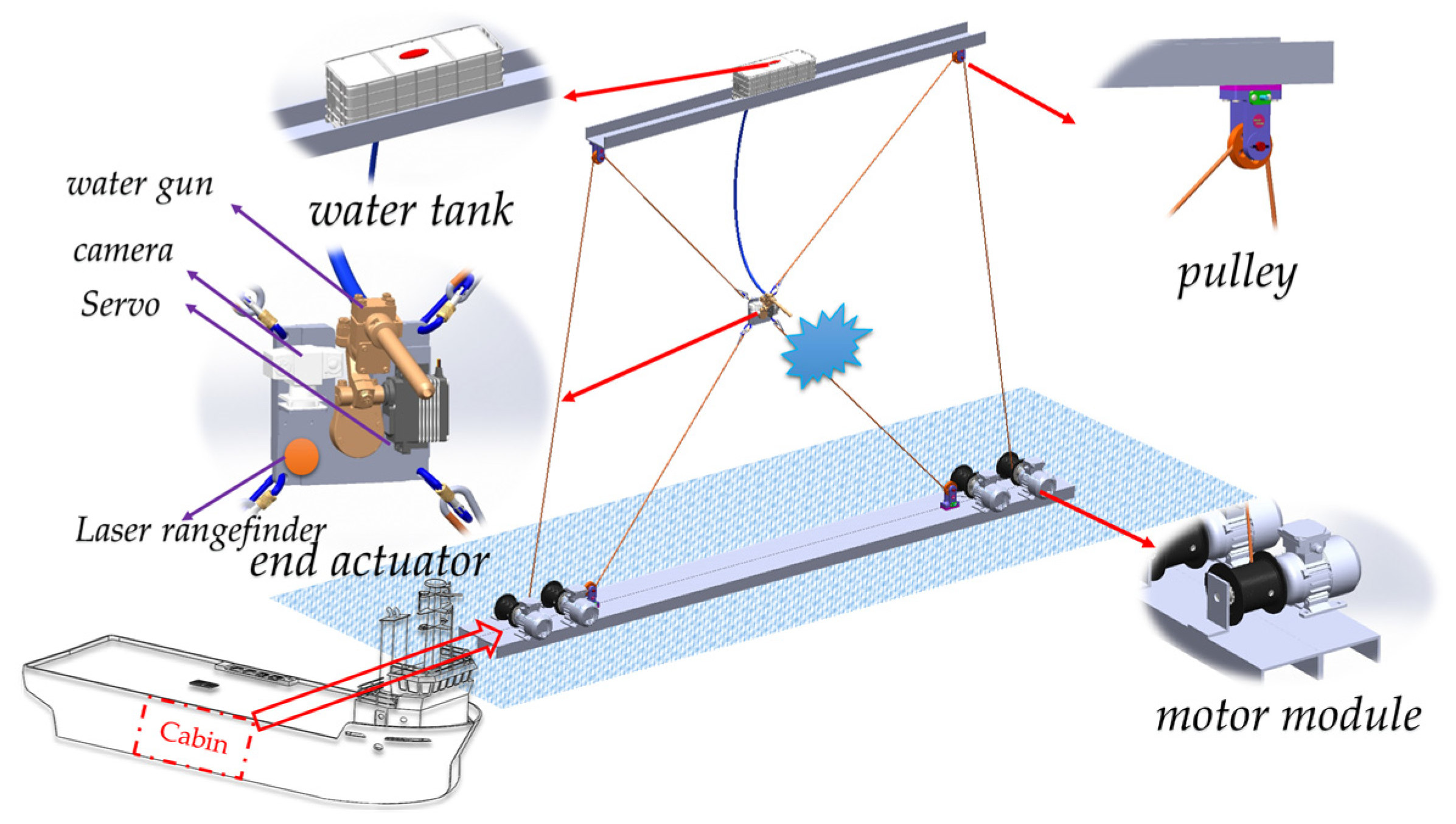
To realize the cargo-hold cleaning operation, the C-DCR’s end-effector needs to move widely within the operating surface. Considering the engineering application, this article adopts a four-cable driven parallel robot. As shown in Figure 1, a water tank, four pulley blocks, four motor modules and an end-effector are deployed in the C-DCR. Among them, the water tank is used to store high-pressure water or cleaning chemicals. The end-effector is equipped with a water gun, a camera and a servo motor. The water gun is used to spray cleaning agent onto the operating surface; the camera is used to monitor operations in real time; and the servo motor is used to drive the rotation of the water gun, so that the robot can adjust the direction of the water outlet according to the shape of the operating surface. The laser rangefinder is used to measure the distance of the end-effector and operating surface in real time.
2.2. Working Principle and Cost
Before the cleaning operation, the C-DCR should be placed in front of the operating surface, the tank filled with cleaning agents and the trajectory of the end-effector planned. During the cleaning operations, the laser rangefinder measures the distance between the end-effector and the operating surface in real time, thereby controlling the water pressure so that the cleaning agent will be sprayed onto the operating area. The camera observes the operation in real time, and the robot can adjust the direction of the water outlet according to the shape of the working surface. At the end of the operation, the lifting equipment lifts the C-DCR out of the cargo hold.
The overall structure of the C-DCR is relatively simple, without special processing parts, which greatly reduces the manufacturing cost. The C-DCR can be mounted to the working area by crane lifting, and the overall implementation cost is mainly crane lifting. The more expensive parts are the motor and the control system, which can be ignored compared to the manual operation cost.
Taking the operating radius of 10 m as an example, the corresponding cost components are shown in Table 1.
The winch speed is calculated as follows:
where = 6.3 m/s is end-effector’s speed; = 0.5 m is winch radius; further, bring and into Equation (1) gives = 2 n/s, which is 120 r/min. Moreover, the motor torque is calculated as follows:
where = 1000 N is upper limit of cable tension; further, bring in to get = 500 Nm.
3. Dynamic Model
As previously mentioned, traditional CDPRs are generally used in fixed-base situations, and the impact of external disturbances on the operation is rarely taken into account. The C-DCR described is suitable for ship cleaning, and this cleaning robot is easily affected by factors such as ship shaking. Therefore, the effects of the ship’s motion excitation as well as external disturbances must be taken into account when modeling the dynamic model.
3.1. Frame Description
The Figure 2 shows the frame distribution of the C-DCR. is the global frame, the is the origin point of the global space, and the direction of coordinate axes , , is the same as the ship frame at the initial moment. is the ship frame, and the origin is located at the center of the bottom of the ship. coincides with the baseline of the longitudinal axis of the ship, coincides with the baseline of the transverse axis of the ship, and direction is determined according to the right-hand rule. The is the end-effector center-of-mass frame, and the origin coincides with the end-effector center-of-mass. The initial axes , and are determined by the posture of the end-effector.
3.2. Frame Transformation
In this article, is used to represent the posture transformation relationship between frame, where represents the reference frame and represents the current frame.
The position vector of the end-effector’s centroid frame in the global frame can be represented as:
A derivative of Equation (3), the velocity vector of the frame with respect to the frame can be calculated:
where is a skew symmetric matrix of .
A further derivative, the acceleration vector can be obtained:
Similarly, the angular velocity and angular acceleration vectors of the frame relative to the frame are respectively:
The posture transformation relationship between different frames has been elaborated to provide theoretical support for the dynamics modeling.
3.3. Dynamic Model of End-Effector
Figure 3 shows the dynamic parameters of C-DCR; the end-effector is affected by gravity, cable tensions and external disturbance forces, where is the pulley connection point and is the end-effector connection point.
The system dynamic model of C-DCR is established based on the Lagrange method. Firstly, the posture of the end-effector is selected as the system generalized coordinate. The kinetic energy of C-DCR includes the translational kinetic energy and rotational kinetic energy of the end-effector. The total kinetic energy of the end-effector is as follows:
where and are the translational speed and angular speed of the end-effector, respectively, and is the inertia matrix of the end-effector in the local frame.
The gravitational potential energy of the end-effector can be expressed as follows:
The Lagrangian function is the difference between the kinetic energy and the potential energy of the system, and the Lagrangian function of the end-effector is expressed as follows:
For a mechanical system with generalized coordinates and Lagrangian function , the motion equation of the system is obtained as:
where is the generalized force of the system. Moreover, substituting each component into the equation of motion, the kinetic equation of the end-effector is obtained as:
where , , , and . Furthermore, the dynamic model of the end-effector obtained by further simplification is:
where is the inertia matrix, is the rotational inertia of the end-effector, is the Coriolis force matrix, , and is the gravity matrix.
The is the external force on the end-effector, including the external disturbance force and the cable tension:
where are the cable tension values, is the external disturbance force to the end-effector, is the external disturbance force, including sea wind, operational reaction force, etc., and is the external disturbance torque, including waves, motor disturbance torque, etc.
The dynamic Jacobi matrix can be specifically expressed as:
where is the unit vector of length of the i-th cable. Further, the dynamic model can be expressed as:
The dynamics model only includes the end-effector, and if the system dynamics model is obtained, the dynamics analysis of the motor part is also considered.
3.4. Dynamic Model of Driving Unit
The C-DCR’s drive system consists of AC servo motors and drives. The motor model is further modeled as follows:
where is the inertia matrix, is the viscous damping coefficient matrix, is the angle of rotation of the winch, and is the difference in length of the i-th cable at moments t and t − 1. is the radius of the winch reel, and is the motor torque.
Combining Equation (17) with Equation (18), the dynamics model of the system can be expressed as:
The system dynamics model is built, and the next section investigates the control strategy.
4. The Modified PD Feedforward Control Strategy
4.1. Controller Design
The fully constrained CDPR is the complex multi-input/output system. The tension value of each cable should be continuous and positive, so a suitable tension optimization algorithm needs to be used to solve the above problem when designing the controller: in this article, on the basis of the traditional PD control strategy, considering the engineering application and the high-speed mobility of the C-DCR. The MPD-FFC is proposed; the control strategy is shown in Figure 4.
Assuming that the desired trajectory of the end-effector is , the control law is designed as follows:
where , are the proportional, integral, and differential gain matrices, respectively, is the generalized inverse matrix of the structure matrix , and can put the cable under tension at all times.
The minimum 2-norm method is used to constrain cable tension. The following relationship is satisfied:
Further, limitations on the range of :
where is the mean value of tension extremes, and are the upper and lower bounds of , respectively.
Combine Equation (20) with Equation (19) and arrange them to obtain the following closed-loop system:
4.2. Stability Analysis of the System
In order to verify whether the control law is stable, it is necessary to prove the stability of the system. Lyapunov stability theory is the basic method for proving the stability of systems [32], and this article constructs the Lyapunov function as:
Derivation of Equation (25):
Bringing Equation (24) to Equation (26):
According to the C-DCR’s dynamic model, it is known that the matrix is skew-symmetric, so Equation (27) can be simplified as:
Since is positive definite matrices, it is easy to know that . Only if , . In other words, when , . According to LaSalle’s invariance theorem, the system is stable.
5. Simulation Experiments
5.1. Simulation Verification
To improve the efficiency of the C-DCR, the movement speed of the end-effector needs to increase. However, the increase in speed will affect the stability of the robot system and increase the positioning error of the end-effector. The dynamic model and control strategy are established in MATLAB/Simulink with the software version R2019a, and the positional signal of the end-effector is used as input to carry out simulation experiments for different working conditions. In addition, the CPU processor is the 12th Gen Intel(R) Core(TM) i5-12400F, and the RAM is 32.0 GB.
During the simulation, the running time is 30 s and the time step of the simulation is set to 1 ms. The control parameters and of MPD-FFC are determined according to the critical proportion method and site commissioning, and the relevant parameters required for simulation are shown in Table 2.
The trajectory of the C-DCR relative to frame is planned to be circular, and the running time is t = 30 s. The initial position of the end-effector is ; the radius of the circle is ; the angular velocity is 0.2 rad/s, and the linear velocity in the XOZ plane is .
The trajectory settings are shown below:
Scenario 1: Simulation analysis for port cleaning operations. Considering that the wave fluctuation adds little excitation to the ship, the simulation does not apply the wave motion. During actual cleaning operations, disturbances such as sea wind and waves can have an impact on robot positioning. In addition, the C-DCR is subjected to the anti-impact force of the water flow in the y-direction. To further verify the robustness of the controller, the external disturbances are given as:
For scenario 1, the numerical analysis of the end-effector’s position tracking under different motion speeds is carried out, and the simulation results are shown in Figure 5.
Figure 5a shows the low-speed motion at the speed of v = 0.6 m/s, Figure 5b shows the medium-speed motion at the speed of v = 3.1 m/s, Figure 5c shows the high-speed motion at the speed of v = 6.3 m/s, and Figure 5d shows the ultra-high-speed motion at the speed of v = 9.4 m/s. As can be seen from Figure 5, the end-effectors all show different degrees of jumping in the Z-direction due to the effect of gravity. However, as the motion gradually changes to a smooth state, the error gradually approaches an acceptable range. By comparing the simulation results, it can be obtained that the larger the speed, the larger the positional tracking error and the more pronounced the start-up jitter in the Z direction. The reason is that at faster speeds, the sudden start of the end-effector requires the cable to provide more tension to achieve the tracking effect, causing the cable to skip. In addition, the tracking steady-state error becomes significantly larger when the speed increases. Because the speed becomes larger, the vibration caused by the inertia of the end-effector becomes larger, which causes a larger error.
As shown in Figure 6, the cable tension variation of the end-effector at different motion speeds is shown. From Figure 6, the smooth and continuous variation of the cable force indicates that the optimized tension is effective.
Scenario 2: Simulation analysis for anchorage cleaning operations. Considering that the ship will be excited by the waves at this time, the wave motion is exerted in the simulation. Sine waves were used to simulate wave motion as follows:
In addition, the external disturbing forces such as sea breeze and current counter-impact to which the C-DCR is subjected become larger compared to scenario 1, and the external disturbance is given as:
For scenario 2, the numerical analysis of the end-effector’s position tracking under low/medium/high-speed motion of C-DCR is carried out, and the trajectory tracking and position tracking error results are shown in Figure 7 and Figure 8 respectively.
From Figure 7, the modified PD feedforward tracking controller can ensure the end-effector with a good trajectory tracking effect under the ship motion and external disturbance forces; moreover, it also has a good tracking effect under high-speed movement.
As can be seen from Figure 8, the steady-state error of low-speed motion of the end-effector is about 1.6 times that of scenario 1; the steady-state error of medium-speed motion of the end-effector is about 3 times that of scenario 1, the steady-state error of high-speed motion of the end-effector is about 4 times that of scenario 1, the steady-state error of ultra-high-speed motion is about 2 times that of scenario 1. It can be seen that the influence of wave motion on the operation of the C-DCR cannot be ignored. In the future, research should be conducted on how to suppress wave interference. It can also be found that the wave excitation does not have a significant effect on the angular error of the end-effector. This is due to the limited angle of rotation of the end-effector under the cable tension.
The cable tension at different speeds are shown in Figure 9. The cable tension change law under the low/medium/high-speed movement is similar to scenario 1, but the tension change law under the ultra-high-speed movement is very different from scenario 1. It shows that the wave excitation has a large effect on the cable tension value in the case of ultra-high speed motion. It also shows that the optimized tension is smooth and continuous at high speeds and below, even when excited by waves. Similar to scenario 1, the optimized cable tension value increases when the speed increases.
The trajectory tracking errors of PD and MPD-FFC for low-speed and high-speed operation with the trajectory are shown in Figure 10 and Figure 11. The PD control law is , the values of and for both controllers are taken to be the same. As can be seen from Figure 10 and Figure 11, the MPD-FFC has higher trajectory tracking accuracy regardless of whether the end-effector is in low/high-speed motion, which is more obvious in high-speed operating conditions. This suggests that for C-DCR, making real-time feedforward corrections can be effective in improving tracking stability.
Based on the numerical analysis results obtained, the data were further analyzed to obtain more valuable research conclusions.
5.2. Discussion of Results
In this article, numerical simulation analysis is carried out for different operating scenarios of the C-DCR. The simulation results show that at the same speed of the end-effector, the trajectory tracking error is larger in the anchorage cleaning operation compared with the port cleaning operation.
The increment of attitude error in the anchorage operation condition compared to the port operation condition is shown in Table 3; the error mean increment here refers to the difference of the arithmetic mean of the errors for different working conditions. The data show that the maximum value of the mean increment of error in the X direction is 0.5405 m, and the maximum value of the mean increment of error in the Z direction is 0.3140 m at ultra-high-speed. The ultra-high speed movement far exceeds the actual operating speed; the error and error increment are too large due to the fast movement of the end-effector, and the positioning accuracy can no longer meet the cleaning operation requirements. It is worth noting that if the movement speed of the end actuator is too fast, it will significantly affect the cleaning operation effect. In order to achieve a good cleaning effect, the end-effector to achieve medium speed movement can meet the operational requirements. The data of low/medium/high speed show that the proposed controller has good trajectory tracking performance for different operating conditions. Moreover, the ship motion causes an increase in the inertial force and moment of inertia of the end-effector, which further affects the trajectory tracking accuracy and leads to a large incremental value of the average error. In addition, it was found that an increase in the speed of the end-effector leads to a larger increment in the average error of the position, which is caused by an increase in the inertia of the motion due to the faster speed. Because the cable tension effectively limits the maximum rotation angle of the end-effector, the increment of the mean angular error decreases gradually during the medium/high/ultra-high-speed motion of the end-effector. This also proves the effectiveness of the proposed tension optimization algorithm.
Table 4 shows the position error mean values of the end-effector with different controllers under ship motion and external disturbances. The data show that the mean value of the positional error of MPD-FFC is significantly lower than PD, the mean value of X-direction error is reduced by 0.2473 m, the mean value of Z-direction error is reduced by 0.1783 m, and the mean value of angle error is reduced by 4.6935 deg. It is further shown that MPD-FFC has higher control accuracy compared to PD.
6. Conclusions
This article proposes a new marine cable-driven parallel cleaning robot and solves the trajectory tracking control problem for different movement speeds. Considering the ship motion excitation and external disturbance, an end-effector dynamics model based on the Lagrange method is established. To keep the cable tight at all times, the minimum 2-norm method is used to optimize the tensions. For the high-speed maneuverability of the C-DCR, a modified PD feedforward controller is designed. The stability of the modeling method and proposed controller is verified by several simulation scenarios. Simulation results show that the error mean of position is 0.22 m and the angular error mean is 2.8° under ship motion and external disturbance, indicating the system can achieve trajectory tracking steadily, smoothly and boundedly in different scenarios. This research will provide theoretical guidance for using the CDPRs in the shipping industry.
In future research work, the problem of cable shaking in the case of a sudden start should be solved. In addition, the prototype experiments should be conducted to further verify the correctness of the theoretical research. Further, through the application of machine vision, IoT and other emerging technologies, C-DCR can be widely applied to hull inspection, cargo transfer and other working conditions.
Author Contributions
Conceptualization, G.H. and J.L.; methodology, G.H. and Y.C.; software, J.L. and Y.C.; validation, G.H. and S.W.; formal analysis, Y.C. and S.W.; resources, H.C.; writing—original draft preparation, G.H., J.L. and Y.C.; writing—review and editing, S.W. and H.C.; supervision, G.H. and S.W.; project administration, G.H. and H.C.; funding acquisition, G.H., H.C. and S.W. All authors have read and agreed to the published version of the manuscript.
Funding
This work was financially supported by the National Key Research and Development Program of China (Project No. 2018YFC0309003), the National Natural Science Foundation of China (Project No. 52101396), and the China Fundamental Research Funds for the Central Universities (Project No. 3132022207, 3132022341). Shenghai Wang was supported by the China Scholarship Council for 18 months study at Georgia Institute of Technology.
Institutional Review Board Statement
Not applicable.
Informed Consent Statement
Not applicable.
Data Availability Statement
Data available on request due to restrictions, e.g., privacy or ethical. The data presented in this study are available on request from the corresponding author. The data are not publicly available due to research group policy.
Conflicts of Interest
The authors declare no conflict of interest.
References
- Anh Vu, L.; Veerajagadheswar, P.; Kyaw, P.T.; Muthugala, M.A.V.J.; Elara, M.R.; Kuma, M.; Nguyen Huu Khanh, N. Towards optimal hydro-blasting in reconfigurable climbing system for corroded ship hull cleaning and maintenance. Expert Syst. Appl. 2020, 170, 114519. [Google Scholar] [CrossRef]
- Adland, R.; Cariou, P.; Jia, H.; Wolff, F.-C. The energy efficiency effects of periodic ship hull cleaning. J. Clean. Prod. 2018, 178, 1–13. [Google Scholar] [CrossRef]
- Eswaramoorthy, S.; John, F.G.P. Wheeled wall climbing robot with suction chamber: A study on forces and moments for stability. In IOP Conference Series: Materials Science and Engineering; IOP Publishing: Bristol, UK, 2021; p. 012065. [Google Scholar]
- Li, H.; Sun, X.; Chen, Z.; Zhang, L.; Wang, H.; Wu, X. Design of a wheeled wall climbing robot based on the performance of bio-inspired dry adhesive material. Robotica 2022, 40, 611–624. [Google Scholar] [CrossRef]
- Akyuz, E.; Celik, M. A methodological extension to human reliability analysis for cargo tank cleaning operation on board chemical tanker ships. Saf. Sci. 2015, 75, 146–155. [Google Scholar] [CrossRef]
- Woods, C.M.C.; Floerl, O.; Jones, L. Biosecurity risks associated with in-water and shore-based marine vessel hull cleaning operations. Mar. Pollut. Bull. 2012, 64, 1392–1401. [Google Scholar] [CrossRef]
- Chen, Y.; Li, J.; Wang, S.; Han, G.; Sun, Y. Dynamic Modeling and Robust Adaptive Sliding Mode Controller for Marine Cable-Driven Parallel Derusting Robot. Appl. Sci. 2022, 12, 6137. [Google Scholar] [CrossRef]
- Bruckmann, T.; Boumann, R. Simulation and optimization of automated masonry construction using cable robots. Adv. Eng. Informatics 2021, 50, 101388. [Google Scholar] [CrossRef]
- Qin, Z.; Liu, Z.; Liu, Y.; Gao, H.; Sun, C.; Sun, G. Workspace analysis and optimal design of dual cable-suspended robots for construction. Mech. Mach. Theory 2022, 171, 104763. [Google Scholar] [CrossRef]
- Ueland, E.; Sauder, T.; Skjetne, R. Optimal Actuator Placement for Real-Time Hybrid Model Testing Using Cable-Driven Parallel Robots. J. Mar. Sci. Eng. 2021, 9, 191. [Google Scholar] [CrossRef]
- Chen, Q.; Zi, B.; Sun, Z.; Li, Y.; Xu, Q. Design and Development of a New Cable-Driven Parallel Robot for Waist Rehabilitation. IEEE/ASME Trans. Mechatron. 2019, 24, 1497–1507. [Google Scholar] [CrossRef]
- Tho, T.P.; Thinh, N.T. Using a Cable-Driven Parallel Robot with Applications in 3D Concrete Printing. Appl. Sci. 2021, 11, 563. [Google Scholar] [CrossRef]
- Iturralde, K.; Feucht, M.; Illner, D.; Hu, R.; Pan, W.; Linner, T.; Bock, T.; Eskudero, I.; Rodriguez, M.; Gorrotxategi, J.; et al. Cable-driven parallel robot for curtain wall module installation. Autom. Constr. 2022, 138, 104235. [Google Scholar] [CrossRef]
- Shao, Z.; Xie, G.; Zhang, Z.; Wang, L. Design and analysis of the cable-driven parallel robot for cleaning exterior wall of buildings. Int. J. Adv. Robot. Syst. 2021, 18, 172988142199031. [Google Scholar] [CrossRef]
- Liu, Z.; Qin, Z.; Gao, H.; Xiang, S.; Sun, G.; Sun, C.; Deng, Z. Mass design method considering force control errors for two-redundant cable-suspended parallel robots. Mech. Mach. Theory 2022, 177, 105043. [Google Scholar] [CrossRef]
- Mamidi, T.K.; Bandyopadhyay, S. Forward dynamic analyses of cable-driven parallel robots with constant input with applications to their kinetostatic problems. Mech. Mach. Theory 2021, 163, 104381. [Google Scholar] [CrossRef]
- Sun, G.; Liu, Z.; Gao, H.; Li, N.; Ding, L.; Deng, Z. Direct method for tension feasible region calculation in multi-redundant cable-driven parallel robots using computational geometry. Mech. Mach. Theory 2020, 158, 104225. [Google Scholar] [CrossRef]
- Wang, R.; Xie, Y.; Chen, X.; Li, Y. Kinematic and Dynamic Modeling and Workspace Analysis of a Suspended Cable-Driven Parallel Robot for Schonflies Motions. Machines 2022, 10, 451. [Google Scholar] [CrossRef]
- Kieu, V.N.D.; Huang, S.-C. Dynamic and Wrench-Feasible Workspace Analysis of a Cable-Driven Parallel Robot Considering a Nonlinear Cable Tension Model. Appl. Sci. 2021, 12, 244. [Google Scholar] [CrossRef]
- Goodarzi, R.; Korayem, M.H.; Tourajizadeh, H.; Nourizadeh, M. Nonlinear dynamic modeling of a mobile spatial cable-driven robot with flexible cables. Nonlinear Dyn. 2022, 108, 3219–3245. [Google Scholar] [CrossRef]
- Baklouti, S.; Courteille, E.; Lemoine, P.; Caro, S. Vibration reduction of Cable-Driven Parallel Robots through elasto-dynamic model-based control. Mech. Mach. Theory 2019, 139, 329–345. [Google Scholar] [CrossRef] [Green Version]
- Zhou, Z.; Zheng, X.; Chen, Z.; Wang, X.; Liang, B.; Wang, Q. Dynamics modeling and analysis of cable-driven segmented manipulator considering friction effects. Mech. Mach. Theory 2021, 169, 104633. [Google Scholar] [CrossRef]
- Choi, S.-H.; Park, K.-S. Integrated and nonlinear dynamic model of a polymer cable for low-speed cable-driven parallel robots. Microsyst. Technol. 2018, 24, 4677–4687. [Google Scholar] [CrossRef]
- Carpio, M.; Saltaren, R.; Viola, J.; Calderon, C.; Guerra, J. Proposal of a Decoupled Structure of Fuzzy-PID Controllers Applied to the Position Control in a Planar CDPR. Electronics 2021, 10, 745. [Google Scholar] [CrossRef]
- Yang, J.; Su, H.; Li, Z.; Ao, D.; Song, R. Adaptive Control with a Fuzzy Tuner for Cable-based Rehabilitation Robot. Int. J. Control. Autom. Syst. 2016, 14, 865–875. [Google Scholar] [CrossRef]
- Kawamura, S.; Kino, H.; Won, C. High-speed manipulation by using parallel wire-driven robots. Robotica 2000, 18, 13–21. [Google Scholar] [CrossRef]
- Xie, F.; Shang, W.; Zhang, B.; Cong, S.; Li, Z. High-Precision Trajectory Tracking Control of Cable-Driven Parallel Robots Using Robust Synchronization. IEEE Trans. Ind. Inform. 2020, 17, 2488–2499. [Google Scholar] [CrossRef]
- Kumar, A.A.; Antoine, J.-F.; Abba, G. Input-Output Feedback Linearization for the Control of a 4 Cable-Driven Parallel Robot. In Proceedings of the 9th IFAC/IFIP/IFORS/IISE/INFORMS Conference on Manufacturing Modelling, Management and Control (IFAC MIM), Berlin, Germany, 28–30 August 2019; pp. 707–712. [Google Scholar]
- Kino, H.; Yahiro, T.; Takemura, F.; Morizono, T. Robust PD control using adaptive compensation for completely restrained parallel-wire driven robots: Translational systems using the minimum number of wires under zero-gravity condition. IEEE Trans. Robot. 2007, 23, 803–812. [Google Scholar] [CrossRef]
- Zhao, Z.; Zhang, L.; Nan, H.; Wang, B. System Modeling and Motion Control of a Cable-Driven Parallel Platform for Underwater Camera Stabilization. IEEE Access 2021, 9, 132954–132966. [Google Scholar] [CrossRef]
- Babaghasabha, R.; Khosravi, M.A.; Taghirad, H.D. Adaptive robust control of fully-constrained cable driven parallel robots. Mechatronics 2015, 25, 27–36. [Google Scholar] [CrossRef]
- Lyapunov, A.M. The general problem of the stability of motion. Int. J. Control 1992, 55, 531–534. [Google Scholar] [CrossRef]
Figure 1.
Robot structure composition.

Figure 2.
Reference frames of C-DCR.

Figure 3.
Dynamic parameters of C-DCR.

Figure 4.
Control strategy of C-DCR.

Figure 5.
Position tracking error at different speeds: (a) Low-speed motion v = 0.6 m/s; (b) Medium speed motion v = 3.1 m/s; (c) High-speed motion v = 6.3 m/s; (d) Ultra-high-speed motion v = 9.4 m/s.
Figure 5.
Position tracking error at different speeds: (a) Low-speed motion v = 0.6 m/s; (b) Medium speed motion v = 3.1 m/s; (c) High-speed motion v = 6.3 m/s; (d) Ultra-high-speed motion v = 9.4 m/s.

Figure 6.
Cable tensions at different speeds: (a) Low-speed motion v = 0.6 m/s; (b) Medium speed motion v = 3.1 m/s; (c) High-speed motion v = 6.3 m/s; (d) Ultra-high-speed motion v = 9.4 m/s.
Figure 6.
Cable tensions at different speeds: (a) Low-speed motion v = 0.6 m/s; (b) Medium speed motion v = 3.1 m/s; (c) High-speed motion v = 6.3 m/s; (d) Ultra-high-speed motion v = 9.4 m/s.

Figure 7.
Trajectory tracking at different speeds: (a) Low-speed motion v = 0.6 m/s; (b) Medium speed motion v = 3.1 m/s; (c) High-speed motion v = 6.3 m/s; (d) Ultra-high-speed motion v = 9.4 m/s.
Figure 7.
Trajectory tracking at different speeds: (a) Low-speed motion v = 0.6 m/s; (b) Medium speed motion v = 3.1 m/s; (c) High-speed motion v = 6.3 m/s; (d) Ultra-high-speed motion v = 9.4 m/s.

Figure 8.
Position tracking error at different speeds: (a) Low-speed motion v = 0.6 m/s; (b) Medium speed motion v = 3.1 m/s; (c) High-speed motion v = 6.3 m/s; (d) Ultra-high-speed motion v = 9.4 m/s.
Figure 8.
Position tracking error at different speeds: (a) Low-speed motion v = 0.6 m/s; (b) Medium speed motion v = 3.1 m/s; (c) High-speed motion v = 6.3 m/s; (d) Ultra-high-speed motion v = 9.4 m/s.

Figure 9.
Cable tensions at different speeds: (a) Low-speed motion v = 0.6 m/s; (b) Medium speed motion v = 3.1 m/s; (c) High-speed motion v = 6.3 m/s; (d) Ultra-high-speed motion v = 9.4 m/s.
Figure 9.
Cable tensions at different speeds: (a) Low-speed motion v = 0.6 m/s; (b) Medium speed motion v = 3.1 m/s; (c) High-speed motion v = 6.3 m/s; (d) Ultra-high-speed motion v = 9.4 m/s.

Figure 10.
Comparison of tracking error of different controllers at v = 0.6 m/s: (a) Position error in X direction; (b) Position error in Z direction; (c) Angle error around the Y-axis.
Figure 10.
Comparison of tracking error of different controllers at v = 0.6 m/s: (a) Position error in X direction; (b) Position error in Z direction; (c) Angle error around the Y-axis.

Figure 11.
Comparison of tracking error of different controllers at v = 6.3 m/s: (a) Position error in X direction; (b) Position error in Z direction; (c) Angle error around the Y-axis.
Figure 11.
Comparison of tracking error of different controllers at v = 6.3 m/s: (a) Position error in X direction; (b) Position error in Z direction; (c) Angle error around the Y-axis.


Table 1.
Operation cost of C-DCR.
| Components and Parts | Parameters | Number | Amount of Money |
|---|---|---|---|
| Winch | Radius is 0.5 m. | 4 | 3000 CNY |
| Motor | Torque is 500 Nm (no reducer). | 4 | 20,000 CNY |
| Mechanical structure | Pulleys, end-effectors, etc. | None | 50,000 CNY |
| Electric control equipment | Siemens PLC 1500. | None | 30,000 CNY |
| Tension sensor | The value ranges from 0–1000 N. | 4 | 10,000 CNY |
| Encoder | Optical encoder | 4 | 10,000 CNY |
| Single operating costs | Lifting and electricity charges | None | 5000 CNY |
Table 2.
Model parameters.
| Parameter Name | Parameter Value | Parameter Name | Parameter Value |
|---|---|---|---|
| m | 5 kg | diag(0.03, 0.03, 0.06) kg/m2 | |
| 0.25 m | 0.25 m | ||
| 40 m | 35 m | ||
| (−1, 0, 2.5)T m | −9.8 kg/m2 | ||
| 10 N | 1000 N |
Table 3.
The increment of position error in different work condition.
| Values | Low-Speed | Medium Speed | High-Speed | Ultra-High-Speed |
|---|---|---|---|---|
| Radius of motion trajectory | 1 m | 5 m | 10 m | 15 m |
| X-direction error mean increment | 0.0250 m | 0.1722 m | 0.1771 m | 0.5405 m |
| Z-direction error mean increment | 0.0347 m | 0.1381 m | 0.1449 m | 0.3140 m |
| Y-axis error mean increment | 0.0095 deg | 2.6117 deg | 2.1010 deg | 1.8673 deg |
Table 4.
The position error mean values with different controllers.
| Controller | X-Direction Error Mean | Z-Direction Error Mean | Y-Axis Error Mean |
|---|---|---|---|
| MPD-FFC | 0.2021 m | 0.2206 m | 2.8023 deg |
| PD | 0.4494 m | 0.3989 m | 7.4965 deg |
Disclaimer/Publisher’s Note: The statements, opinions and data contained in all publications are solely those of the individual author(s) and contributor(s) and not of MDPI and/or the editor(s). MDPI and/or the editor(s) disclaim responsibility for any injury to people or property resulting from any ideas, methods, instructions or products referred to in the content. |
© 2023 by the authors. Licensee MDPI, Basel, Switzerland. This article is an open access article distributed under the terms and conditions of the Creative Commons Attribution (CC BY) license (https://creativecommons.org/licenses/by/4.0/).
Share and Cite
MDPI and ACS Style
Han, G.; Li, J.; Chen, Y.; Wang, S.; Chen, H. Dynamic Modeling and Motion Control Strategy of Cable-Driven Cleaning Robot for Ship Cargo Hold. J. Mar. Sci. Eng. 2023, 11, 87. https://doi.org/10.3390/jmse11010087
AMA Style
Han G, Li J, Chen Y, Wang S, Chen H. Dynamic Modeling and Motion Control Strategy of Cable-Driven Cleaning Robot for Ship Cargo Hold. Journal of Marine Science and Engineering. 2023; 11(1):87. https://doi.org/10.3390/jmse11010087
Chicago/Turabian StyleHan, Guangdong, Jian Li, Yizong Chen, Shenghai Wang, and Haiquan Chen. 2023. "Dynamic Modeling and Motion Control Strategy of Cable-Driven Cleaning Robot for Ship Cargo Hold" Journal of Marine Science and Engineering 11, no. 1: 87. https://doi.org/10.3390/jmse11010087
Note that from the first issue of 2016, this journal uses article numbers instead of page numbers. See further details here.