
One-Way Vibration Absorber


1
Aeroakustik Stuttgart, D-81679 Munich, Germany
2
Aeroakustik Stuttgart, D-42799 Leichlingen, Germany
*
Author to whom correspondence should be addressed.
Acoustics 2022, 4(3), 554-563; https://doi.org/10.3390/acoustics4030034
Submission received: 4 May 2022
/
Revised: 5 July 2022
/
Accepted: 7 July 2022
/
Published: 13 July 2022
(This article belongs to the Special Issue Elastic Wave Scattering in Heterogeneous Media)
Abstract
:A vibration absorber consisting of a one-dimensional waveguide with a reflectionless termination extracts vibrational energy from a structure that is to be damped. An optimum energy dissipation occurs for the so-called power adjustment, i.e, the same level of resistance and the opposite reactance of structure and absorber. The dimensioning of these impedance parameters on the base of the classic second order “two-way” wave equation provides analytical solutions for a few simple waveguide shapes; solutions for all other waveguides are only accessible via numerical finite-element computation. However, the competing first order “one-way” wave equation allows for an analytical conception of both the known broadband vibration absorber and the “Acoustic Black Hole” absorber. For example, for an exponential waveguide, the two-way calculation shows no resistance (and hence no real wave propagation) below a cut-off frequency, while the one-way wave equation predicts absorption in the whole frequency range.
1. Introduction
Mironov’s title “Propagation of a flexural wave in a plate whose thickness decreases smoothly to zero in a finite interval” [1] describes a two-dimensional circular plate with a decreasing local bending wave velocity c towards its center due to a strength reduction. The extreme case with signifies a singularity that deflects bending waves to the center and dissipates the energy without reflections.
The article remained unnoticed for a long time—until Krylov [2], in 2004, described such an energy sink as an “Acoustic Black Hole” (ABH). After this, an exponentially growing interest arose: in 2021, Google Scholar listed 56 scientific articles regarding ABH and vibration topics. By this year, numerous ABH related patents were filed worldwide: 62 in China, four in USA/Canada, three in Europe and one in South Korea [3]. An overview of the ABH research can be found in [4].
By using a one-dimensional analytical model for a inhomogeneous lossless fluid, Maysenhölder showed that the ABH effect is not restricted to bending waves [5]. From his point of view, energy conservation is still valid because the wave energy does not disappear in the ABH’s energy sink but is stored: “The wave velocity decreases towards the singularity . So, the wave energy is transported with decreasing speed, it is accumulated up and stored”.
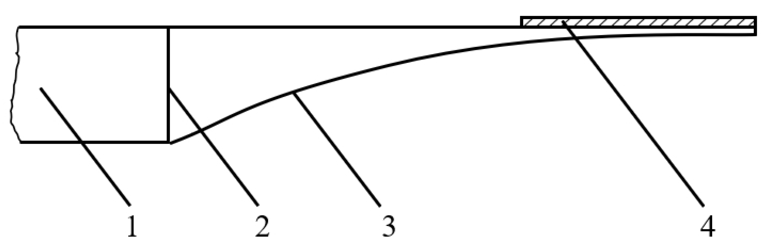
To use Mironov’s mathematical model in a more robust representation, Krylov took, instead of the two-dimensional circular ABH plate, a compact one-dimensional ABH rod element and added a damping layer on the tapered end [2], see Figure 1.
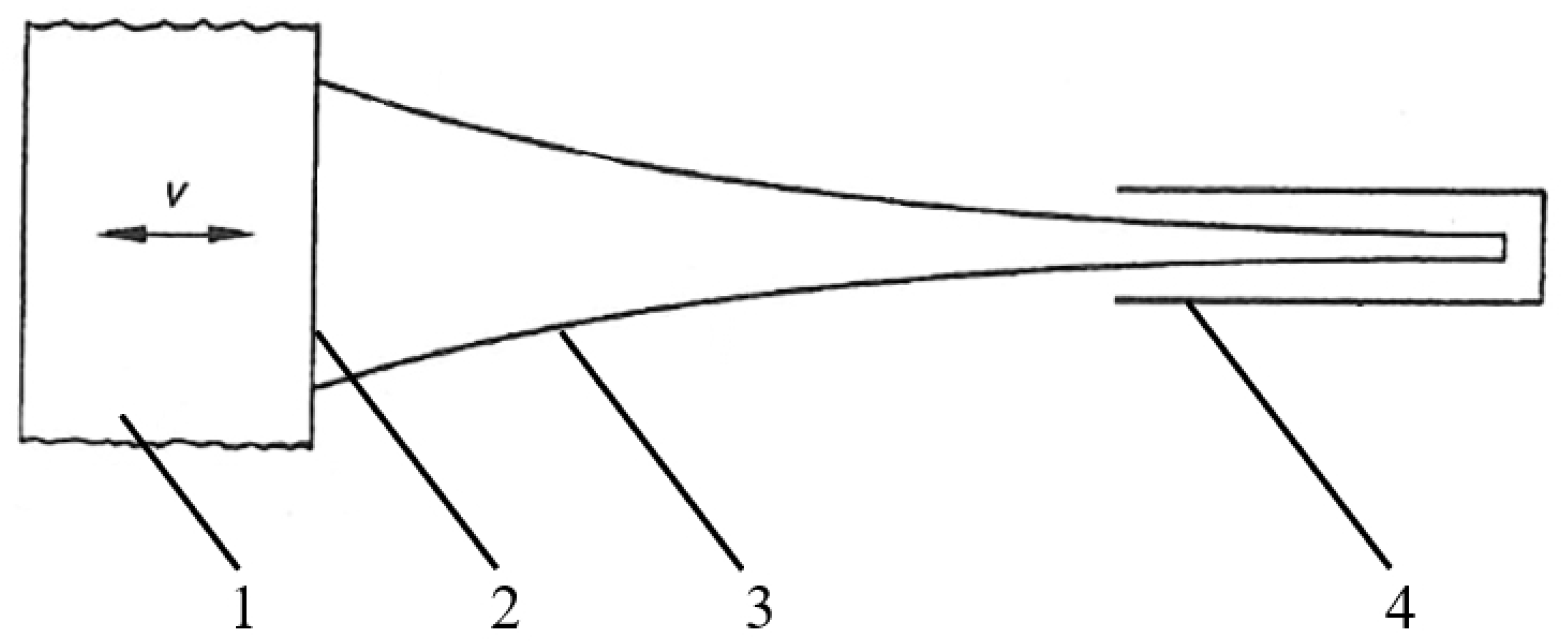
The comparison of Figure 1 with Figure 2 reveals, that Krylov’s approach resulted in the known “broadband vibration absorber” (BVA) [6,7,8]. This one-dimensional tapered waveguide is coupled at one end, in a force-fitting manner, to the vibrating structure, and at the other end, a reflectionless termination is achieved by pathway damping.
Generally, a phase shift [rad] of the pressure vs. the velocity amplitude [m/s], extracts damping power N [W] from the vibrating structure according to the formula
A cylindrical waveguide with constant parameters (cross section area [m2], density [kg/m3] and wave velocity [m/s]) has a real impedance with the resistance [kg/s]
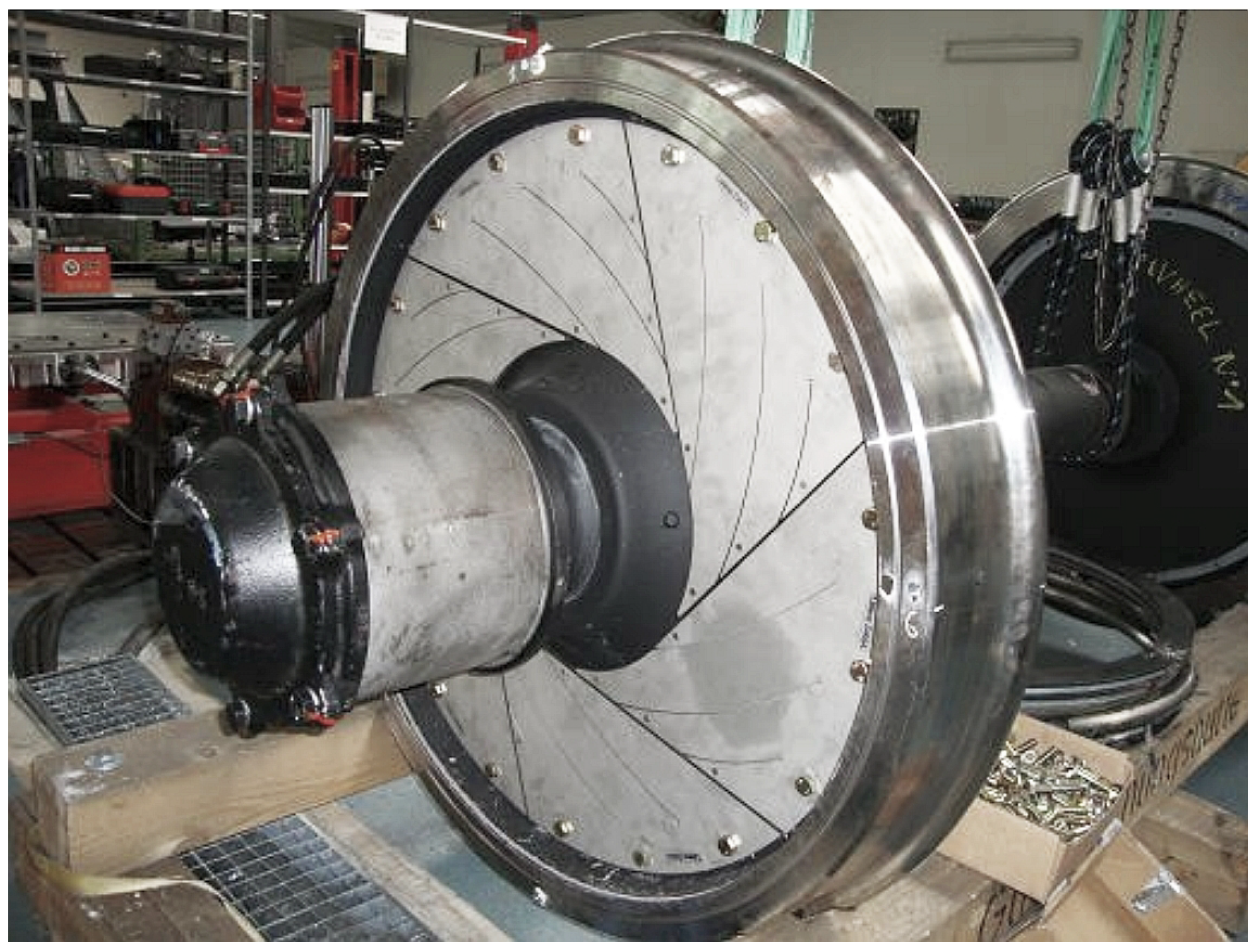
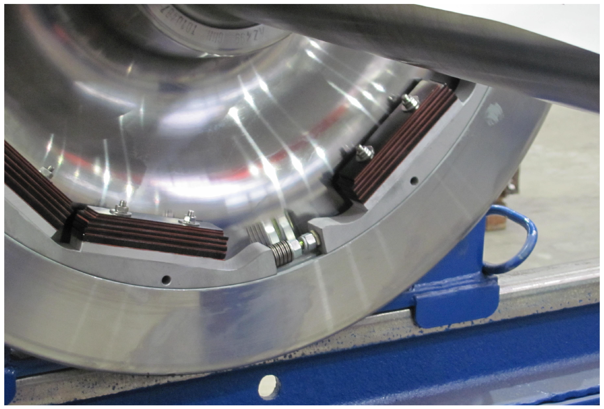
The maximum damping occurs in the case of power adjustment, i.e., for equal resistance and opposite reactance of structure and absorber. Metals have a high specific impedance [kg/m2s], thus they are predestined as waveguide materials. A disadvantage is their low loss factors [-], and therefore the pathway damping has to be increased. Figure 3 shows a railway wheel absorber as a bending waveguide consisting of two metal crescent plates with an intermediate viscous damping layer. In Figure 4 and Figure 5, the pathway damping of a longitudinal waveguide is achieved by alternating layers of metal and plastic plates.
Conventionally, the design of vibration absorbers is based on the classical Cauchy equation of motion. This is a second order partial differential Equation (PDE), which has two equivalent solutions for describing waves in opposite directions, hence, the name “two-way wave equation”. The calculation of vibrations within an inhomogeneous rod material with a variable rod cross-section is only analytically possible for a few specific contours. In numerical FD calculations, irregular phantom effects occur due to an inherent ambiguity (no unique wave propagation direction).
The aim of this investigation is the calculation of a one-dimensional one-way vibration absorber. For this purpose, the existing “two-way” wave equation has to be rewritten as a “one-way” wave equation. Then, the Webster horn equation, also based on the two-way wave theory, will be adapted to the one-way approach as well. The two-way/one-way predictions are compared with horn waveguide measurements.
2. Derivation of the One-Way Wave Equation and One-Way Horn Equation
2.1. Conversion from the Two-Way Wave Equation to the One-Way Wave Equation
An inhomogeneous solid with cartesian coordinates [m] has the local isotropic elastic modulus [Pa], the local density [kg/m3] and the longitudinal wave velocity:
A longitudinal wave field characterized by the vectorial elastic displacement [m] and the stress tensor [Pa] is calculated according to the first Cauchy law of motion (, ):
This vectorial equation describes a local force equilibrium of d’Alembert’s inertia force [N/m3] and the divergence force of stress tensor . This second order partial differential Equation (PDE) has two independent solutions, hence the name “two-way wave equation”. Due to this ambiguity, irregular phantom effects occur in numerical (for example seismic) finite-element or also finite-difference wave calculations. For their elimination, a high number of auxiliary equations have been developed; however, none of these approaches prevailed as an accepted standard solution.
Due to these difficulties, the conventional force equilibrium was hypothetically replaced by an impulse equilibrium, more precisely: impulse flow equilibrium [16]. This hypothesis can be confirmed by two independent derivations: impedance theorem [17] and factorization [18]. Force and impulse are related and differ by one differentiation level. For this purpose, the impulse unit Huygens Hy = mass times velocity [Hy = mkg/s] was used after being introduced by the Karlsruhe KPK school.
Thus, for a particle velocity [m/s], the local impulse [Hy/m3] exists. If the particle velocity propagates with the vectorial wave velocity [m/s], the dyadic product provides a kinetic impulse flow of the dimension [Hy/sm2], i.e., Huygens[Hy] per unit time and area. The elastic deformation induces the potential impulse flow [Hy/sm2]. While Cauchy’s force balance is valid for an infinitesimal volume element , kinetic and potential impulse fulfill a local equilibrium in each field point [16]:
This tensor equation can be scalarly multiplied with the wave velocity vector . With the material law , Equation (1), and the time independence of the elasticity modulus with results the first order vectorial partial differential equation:
To calculate longitudinal waves in a one-dimensional vibration absorber, the scalar form is sufficient. With and , the equation is obtained.
2.2. Introduction of the One-Way Webster Horn Equation
A waveguide with a cross-section area is given. The pressure of a longitudinal wave with wave velocity c is governed by the Webster horn equation:
Pierce [19] transformed Equation (5) from the field variable pressure p to the combined field variable [Pa m] (#, ##, ##):
The left side consists of the wave equation for the combined field variable (). The squared expression ( with the specific sound intensity defined as [W/m2] is a measure for the sound power [W] transported across the waveguide cross-section area A. Equal power with requires that the disturbance element on the right side of the equation disappears:
The solution of this differential equation is:
and this represents a conical waveguide with the opening angle [sterad]. For , this corresponds to a spherical wave. All the other cross-section profiles, including the often used exponential horn do not satisfy the condition Due to this discrepancy, the one-way Webster equation was derived in [20]:
Since waveguide cross section area A is time-independent, identity is valid, and a one-way wave equation with the combined field variable results:
In contrast to (5), there is a constancy of ().
3. One-Way Vibration Absorber: Resulting Equations, Solutions and Impedances
The waveguide parameters # of the 1D vibration absorber shown in Figure 6 depend on x in the general case, i.e., # = #. Continuity of the functions # and ## is assumed. In addition to the cross-section A [m2], the characteristic diameter [m] is introduced.
Elastic modulus E [Pa] and density [kg/m3] give the longitudinal wave velocity (1). The field variable is the longitudinal displacement of a wave with circular frequency [rad/s] and wavelength [m]. The stringent 1D condition requires . Reflectionless termination requires ## . According to the task, the "one-way" wave equation is used. The equation for the general case is as follows
With the restriction to wave motions of the angular frequency [rad/s] one obtains the time-independent notation with
According to Equation (14) can also be directly integrated for the general case of an inhomogeneous x-dependent wave velocity and for the combined field variable the respective Helmholtz equation is obtained as solution (with integration constant = amplitude at [])
As can be verified by substitution, this corresponds to a wave of angular frequency traveling in -direction
Displacement , particle velocity and gradient are calculated
Therefore, it is possible to calculate further characteristic values of the waveguide. The quotient of compressive stress and particle velocity , gives the specific impedance [kg/sm2]. With ## at the waveguide beginning the impedance [kg/s] with real resistance and imaginary reactance follows
Table 1 shows the relations for general and specific waveguide properties.
4. Comparison of Two-Way/One-Way Predictions vs. Measurement
For a quantitative comparison, a 1D waveguide consisting of homogeneous material and and with an exponential cross-sectional area is considered ( [1/m] = exponent)
According to the second order two-way PDE based on the classic force equilibrium (“force concept”), the semi-infinite exponential horn waveguide with has the input impedance and the cut-off frequency [1/s] [21]. Below cut-off frequency the impedance is imaginary and no real power is transmitted.
In contrast to this, the first order one-way PDE based on the impulse flow equilibrium (“impulse concept”) does not have a cut-off frequency and the impedance follows as [22]
In Figure 7, the resistances and reactances of the two-way and the one-way approach are compared. The resistances and the reactances significantly differ for low frequencies.
It can be proven that real wave propagation also occurs below cut-off frequency . The results of an measurement [23] (see Figure 8 and Figure 9), with an acoustical exponential waveguide are in line with the one-way horn equation, i.e., the waves propagate with constant local wave velocity (speed of sound 343 m/s), see Figure 10.
5. Conclusions
The conventional broadband vibration (BVA) absorber by Bschorr/Albrecht and the acoustic black hole (ABH) absorber by Kyrov work according to the same principle: both are rod-shaped waveguides, one end is force-fitted to the vibrating structure to be damped, and the other end is reflectionless due to pathway damping.
The characteristic criteria for the damping performance is the absorber’s resistance at the coupling base area. The maximum damping occurs for power adjustment, i.e., the vibration absorber and the structure have equal resistance and equal but opposite reactance.
The calculation of the vibration absorber according to the conventional two-way wave equation only provides analytical solutions for a few waveguide contours; in the general case, numerical methods have to be used. Using two independent methods, the impedance theorem [17] and the factorization [18], it was possible to reduce the two-way wave equation to the one-way wave equation. Mathematically, this corresponds to a factorization of second-order PDE, which is generally only numerically solvable, into a first-order PDE. The first-order PDEs can be solved via quadrature. The first-order approach also aligns with the waveguide measurements at a reflectionless terminated exponential horn.
Author Contributions
Conceptualization, methodology and formal analysis; O.B.; writing—original draft preparation; O.B. and H.-J.R.; investigation; H.-J.R.; writing—review and editing; O.B. and H.-J.R.; and visualization and translation; H.-J.R. All authors have read and agreed to the published version of the manuscript.
Funding
This research received no external funding.
Data Availability Statement
Not applicable.
Conflicts of Interest
The authors declare no conflict of interest.
References
- Mironov, M.A. Propagation of a flexural wave in a plate whose thickness decreases smoothly to zero in a finite interval. Sov. Phys. Acoust. 1988, 34, 318–319. [Google Scholar]
- Krylov, V.V. New type of vibration dampers utilising the effect of acoustic black holes. Acta Acust. United Acust. 2004, 90, 830–837. [Google Scholar]
- European Patent Office, Patent Database, Search for “Acoustic Black Hole”. 2022. Available online: https://worldwide.espacenet.com/patent/search/?q=ctxt%20%3D%20%22Acoustic%20black%20hole%22 (accessed on 1 May 2022).
- Pelat, A.; Gautier, F.; Conlon, S.C.; Semperlotti, F. The acoustic black hole: A review of theory and applications. J. Sound Vib. 2020, 476, 115316. [Google Scholar] [CrossRef]
- Maysenhölder, W. Perfekte Absorption ohne Dämpfung: Schön wär’s! [Perfect Absorption w/o damping: Would be great!]. In Proceedings of the 20th Workshop Physical Acoustics “Sound propagation in inhomogeneous Media”, Bad Honnef, Germany, 14–15 November 2013. [Google Scholar]
- Bschorr, O. Schwingungsdämpfer für Körperschall [Vibration Absorber for Structure-Borne Noise]. DE Patent DE2229420A1, 14 February 1974. [Google Scholar]
- Bschorr, O. Breitbandiger Schwingungsdämpfer [Broadband Vibration Absorber]. DE Patent DE2412672A1, 18 September 1975. [Google Scholar]
- Bschorr, O.; Albrecht, H. Schwingungsabsorber zur Reduzierung des Maschinenlärms [Vibration Absorber for the Reduction of Machine Noise]. VDI-Zeitschrift 1979, 121, 253. [Google Scholar]
- Betgen, B.; Bouvet, P.D.; Thompson, J.; Demilly, F.; Gerlach, T. Assessment of the efficiency of railway wheel dampers using laboratory methods within the STARDAMP project. In Proceedings of the Acoustics 2012 Nantes Conference, Nantes, France, 23–27 April 2012; pp. 3733–3738. [Google Scholar]
- Weber, W.; Paluszkiewicz, M.; Albrecht, H.; Brühl, S.; Bschorr, O.; Masche, A.G. Messerschmidt Bölkow Blohm: Körperschalldämpfer für ein Laufrad [Vibration Damper for a Wheel]. DE Patent DE3119497A1, 9 December 1982. [Google Scholar]
- Gerlach, T.; Notthoff, N. Gutehoffnungshütte Radsatz GmbH: Schallabsorber-Element und Schallabsorber für ein Schienenfahrzeug-Rad sowie damit ausgestattetes Rad [Sound Absorber Element and Sound Absorber for a Railway Wheel and a Respectively Equipped Wheel]. EP1892122B1, 27 February 2008. [Google Scholar]
- Gramowski, C.; Gerlach, T. Entering the Real Operation Phase: Design, Construction and Benefit Verification of Freight Wheel Noise Absorber. In Proceedings of the 13th International Workshop on Railway Noise, Ghent, Belgium, 16–20 September 2019. [Google Scholar]
- Schrey&Veit. Product Brochures: Rail Dampers, Innovative Noise Mitigation on Railways; Product Information about Raildampers VICON AMSA 54 FS; Schrey&Veit: Sprendlingen, Germany, 2022. [Google Scholar]
- Gramowski, C. Schienendämpfer, Warum variiert die Lärmreduktion? [Rail damper, why varies the noise noise reduction?]. EI-Eisenbahningenieur 2013, 64, 70–75. [Google Scholar]
- Betgen, B.; Bouvet, P.; Squicciarini, G.; Thompson, D.J. The STARDAMP Software: An Assessment Tool for Wheel and Rail Damper Efficiency. In Proceedings of the AIA-DAGA 2013 Conference on Acoustics, Merano, Italy, 18–21 March 2013; p. 4. [Google Scholar]
- Bschorr, O. Deviationswellen in Festkörpern [Devitation Waves in Solids]. In Proceedings of the DAGA 2014—40th German Annual Conference of Acoustics, Oldenburg, Germany, 10–13 March 2014; pp. 80–81. [Google Scholar]
- Bschorr, O.; Raida, H.-J. One-Way Wave Equation Derived from Impedance Theorem. Acoustics 2020, 2, 167–170. [Google Scholar] [CrossRef]
- Bschorr, O.; Raida, H.-J. Factorized one-way Wave Equations. Acoustics 2021, 3, 717–722. [Google Scholar] [CrossRef]
- Pierce, A. Acoustics: An Introduction to its Physical Principles and Applications; Acoustical Society of America through the American Institute of Physics: Woodbury, NY, USA, 1994; p. 360. [Google Scholar]
- Bschorr, O. Wellenleitung im eindimensionalen Festkörper [Wave Propagation in one-dimensional solids]. In Proceedings of the DAGA 2015—41th German Annual Conference of Acoustics, Nürnberg, Germany, 16–19 March 2015; pp. 828–829. [Google Scholar]
- Lerch, R.; Sessler, M.; Wolf, D. Technische Akustik, Grundlagen und Anwendungen [Technical Acoustics, Foundations and Applications]; Springer: Berlin, Germany, 2009; p. 136. [Google Scholar]
- Bschorr, O. Hornleiter nach dem Impulskonzept [Horn Waveguide according to the Impulse Concept]. In Proceedings of the DAGA 2016—42th German Annual Conference of Acoustics, Aachen, Germany, 14–17 March 2016; pp. 268–269. [Google Scholar]
- Raida, H.-J.; Bschorr, O. Konventionelles Kräftegleichgewicht vs. hypothetisches Impulsflussgleichgewicht [Conventional force equilibrium vs. hypothetical impulse flow equilibrium]. In Proceedings of DAGA 2018–44th German Annual Conference of Acoustics, Munich, Germany, 19–22 March 2018; pp. 828–831. [Google Scholar]
Figure 1.
Acoustic Black Hole (ABH) vibration absorber, technical principle as in Krylov (2004) [2]: 1 = structure to be damped, 2 = base area , 3 = tapered waveguide and 4 = damping layer. Since the mathematical singularity with wave velocity is technically not feasible, a damping layer is added for a reflectionless termination.

Figure 2.
Broadband vibration absorber (BVA) according to Bschorr/Albrecht (1979) [6,7,8]: 1 = structure to be damped, 2 = base area , 3 = tapered waveguide and 4 = damping layer. A one-dimensional absorber with base area [m2], density [kg/m3] and longitudinal wave velocity [m/s] achieves a maximum resistance [kg/s]. Coupled to a vibrating structure with mean velocity v [m/s] causes the damping power 1/2 [W].

Figure 3.
Railway wheel absorber (GHH-VALDUNES, Gutehoffnungshütte (GHH), Oberhausen, Germany, reprinted with permission from Ref. [9], Copyright 2012, GHH-Radsatz) consisting of two metal crescent plates with an constrained viscous damping layer as a bending waveguide to reduce wheel-radiated squeaking noises while cornering [10,11].

Figure 4.
Railway wheel absorber (VICON RASA RSI, Schrey & Veit GmbH, Sprendlingen, Germany, reprinted with permission from Ref. [12], Copyright 2019, Schrey &Veit) comprising a stack of alternating metal and plastic plates as a longitudinal waveguide absorber. Tests proved a reduction in the noise level LAeq, Tp (ISO 3095) by about 4 dB.

Figure 5.
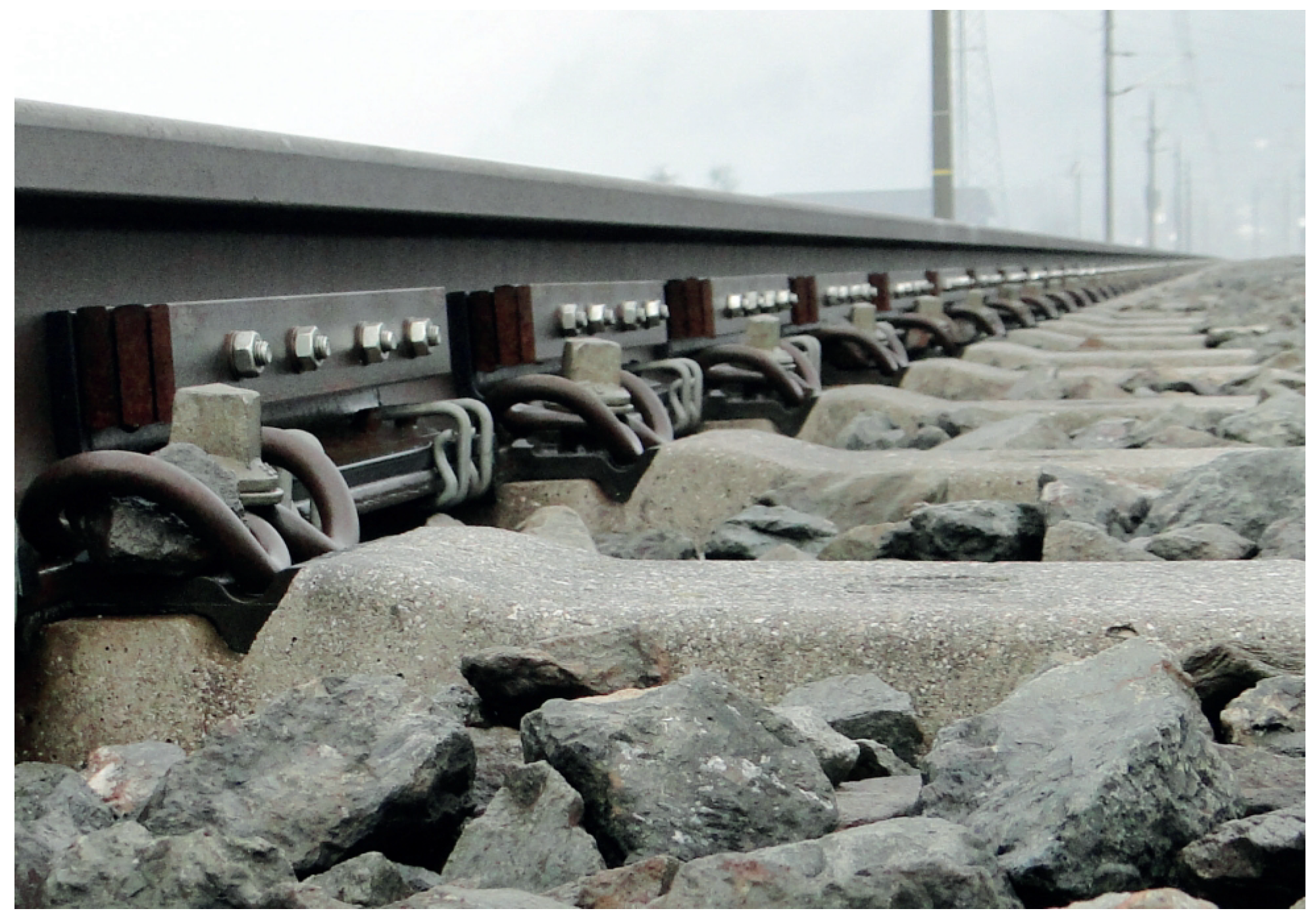
Rail absorber (VICON AMSA 60 VS, Schrey & Veit GmbH, Sprendlingen, Germany, reprinted with permission from Ref. [13], Copyright 2022, Schrey &Veit) consisting of a stack of alternating metal and plastic plates acting for the reduction of noise from vibrating rails, which are a further major sound emitter in addition to the rail wheels [14,15].
Figure 5.
Rail absorber (VICON AMSA 60 VS, Schrey & Veit GmbH, Sprendlingen, Germany, reprinted with permission from Ref. [13], Copyright 2022, Schrey &Veit) consisting of a stack of alternating metal and plastic plates acting for the reduction of noise from vibrating rails, which are a further major sound emitter in addition to the rail wheels [14,15].

Figure 6.
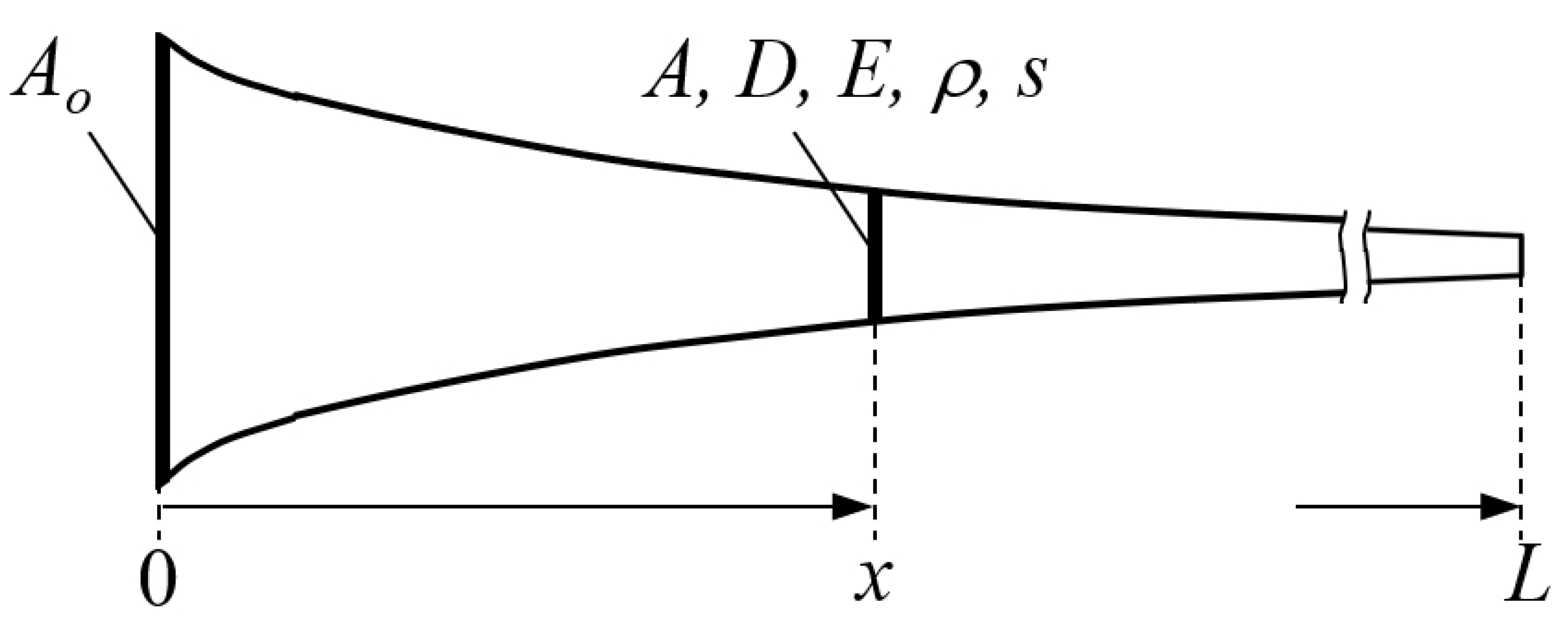
1D waveguide with coordinate x [m] and for the description of a traveling longitudinal wave in the direction; cross-section area A [m2] (characteristic diameter ), elasticity modulus E, density , local displacement s and waveguide length L [m].
Figure 6.
1D waveguide with coordinate x [m] and for the description of a traveling longitudinal wave in the direction; cross-section area A [m2] (characteristic diameter ), elasticity modulus E, density , local displacement s and waveguide length L [m].

Figure 7.
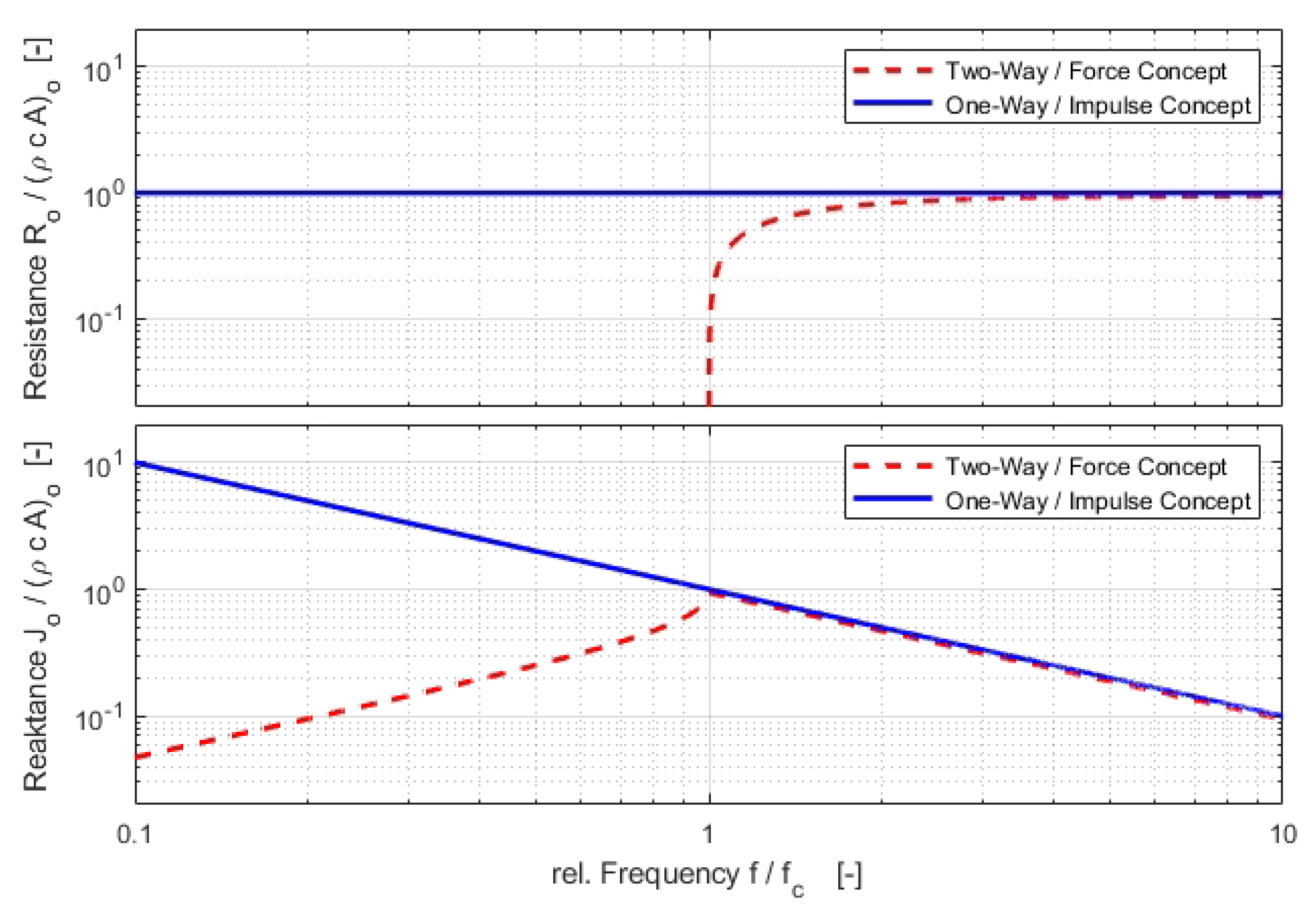
For the semi-infinite exponential horn with the contour the two-way based “force concept” predicts no resistance below the cut-off frequency , for frequencies , there is asymptotic approximation towards . In contrast, according to the one-way based “impulse concept” a constant resistance exists over the entire frequency range. For the semi-infinite exponential horn both concepts have the same reactance; however, for frequencies the values differ significantly.
Figure 7.
For the semi-infinite exponential horn with the contour the two-way based “force concept” predicts no resistance below the cut-off frequency , for frequencies , there is asymptotic approximation towards . In contrast, according to the one-way based “impulse concept” a constant resistance exists over the entire frequency range. For the semi-infinite exponential horn both concepts have the same reactance; however, for frequencies the values differ significantly.

Figure 8.
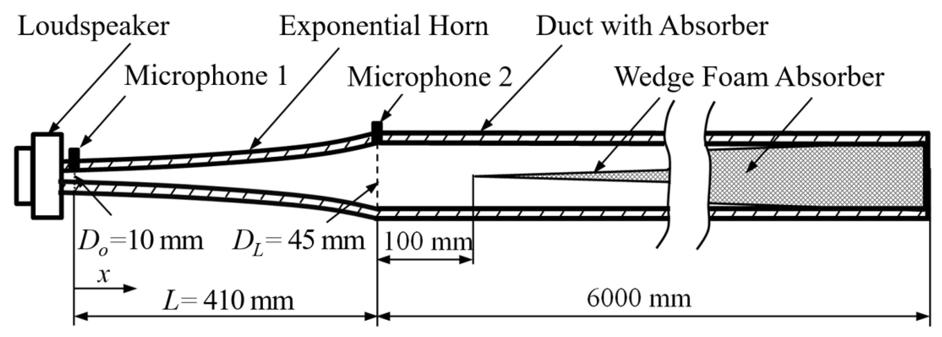
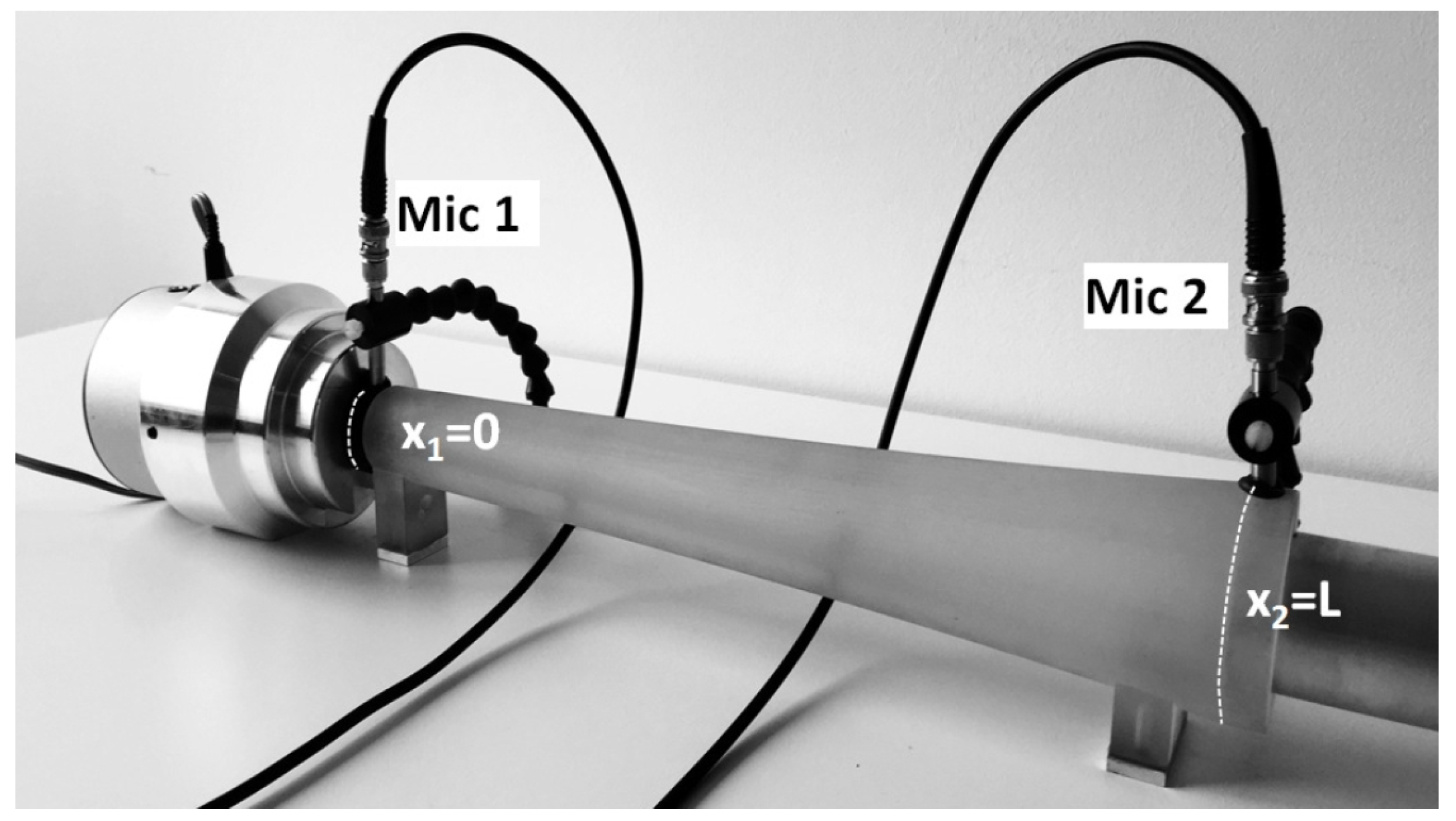
Experimental setup: loudspeaker, exponential horn, reflectionless termination with wedge foam absorber (6 m) to avoid backtraveling waves; microphones at , [23].
Figure 8.
Experimental setup: loudspeaker, exponential horn, reflectionless termination with wedge foam absorber (6 m) to avoid backtraveling waves; microphones at , [23].

Figure 9.
Exponential horn with length L = 410 mm, = 10 mm, = 45 mm, manufactured with rapid prototyping (accuracy 50 ), wall thickness 15 mm [23].
Figure 9.
Exponential horn with length L = 410 mm, = 10 mm, = 45 mm, manufactured with rapid prototyping (accuracy 50 ), wall thickness 15 mm [23].

Figure 10.
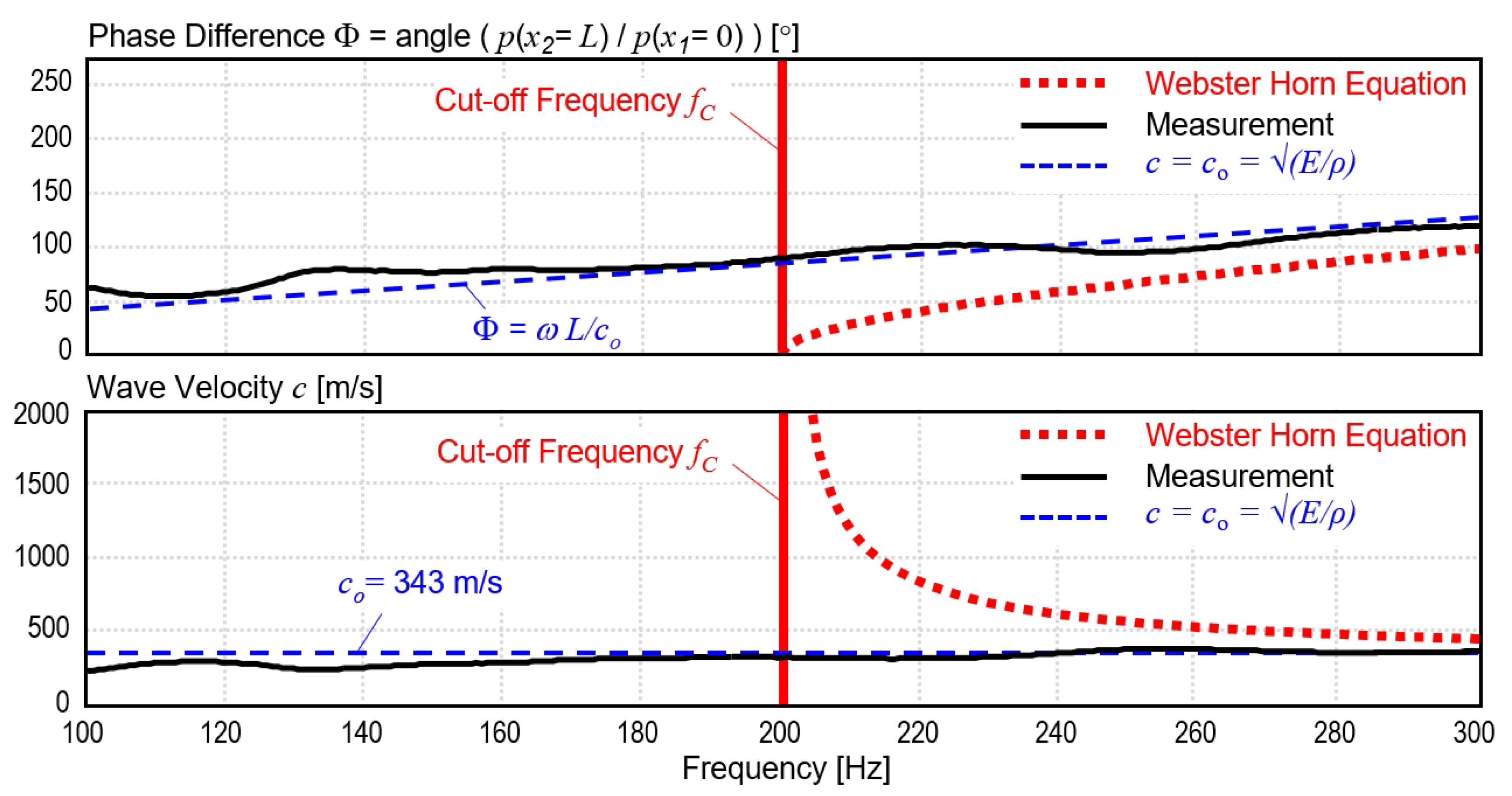
Exponentional horn measurement [23]. The top graph shows the measured phase angle and the bottom graph the calculated wave velocity . The sound propagates with a linear phase and a wave velocity of 343 m/s, see black lines. The predictions of the Webster horn equation are displayed with red lines. The conditions for conformity with the Principle of Locality () are shown with blue lines. The measurement indicates, that the sound waves in the exponential horn with reflectionless termination travel with speed of sound at/below cut-off frequency = 200 Hz. This is in contrast to the predictions of the Webster horn equation.
Figure 10.
Exponentional horn measurement [23]. The top graph shows the measured phase angle and the bottom graph the calculated wave velocity . The sound propagates with a linear phase and a wave velocity of 343 m/s, see black lines. The predictions of the Webster horn equation are displayed with red lines. The conditions for conformity with the Principle of Locality () are shown with blue lines. The measurement indicates, that the sound waves in the exponential horn with reflectionless termination travel with speed of sound at/below cut-off frequency = 200 Hz. This is in contrast to the predictions of the Webster horn equation.


Table 1.
Overview: 1D one-way wave equations, solutions; generic case and different waveguide materials and contours (D [m] = ). A real elasticity modulus E describes the lossless case. A complex elasticity modulus with lossfactor [-] considers absorption.
Table 1.
Overview: 1D one-way wave equations, solutions; generic case and different waveguide materials and contours (D [m] = ). A real elasticity modulus E describes the lossless case. A complex elasticity modulus with lossfactor [-] considers absorption.
| Reference | Generic | Homogeneous | Cylindrical | |
|---|---|---|---|---|
| Plane Wave | Waveguide | Waveguide | Waveguide | |
| Material | , | , | . | , |
| Contour | ||||
| 3D Equation | ||||
| 1D Equation | ||||
| 1D Solution | ||||
| Impedance | ||||
| Resistance |
Publisher’s Note: MDPI stays neutral with regard to jurisdictional claims in published maps and institutional affiliations. |
© 2022 by the authors. Licensee MDPI, Basel, Switzerland. This article is an open access article distributed under the terms and conditions of the Creative Commons Attribution (CC BY) license (https://creativecommons.org/licenses/by/4.0/).
Share and Cite
MDPI and ACS Style
Bschorr, O.; Raida, H.-J. One-Way Vibration Absorber. Acoustics 2022, 4, 554-563. https://doi.org/10.3390/acoustics4030034
AMA Style
Bschorr O, Raida H-J. One-Way Vibration Absorber. Acoustics. 2022; 4(3):554-563. https://doi.org/10.3390/acoustics4030034
Chicago/Turabian StyleBschorr, Oskar, and Hans-Joachim Raida. 2022. "One-Way Vibration Absorber" Acoustics 4, no. 3: 554-563. https://doi.org/10.3390/acoustics4030034